
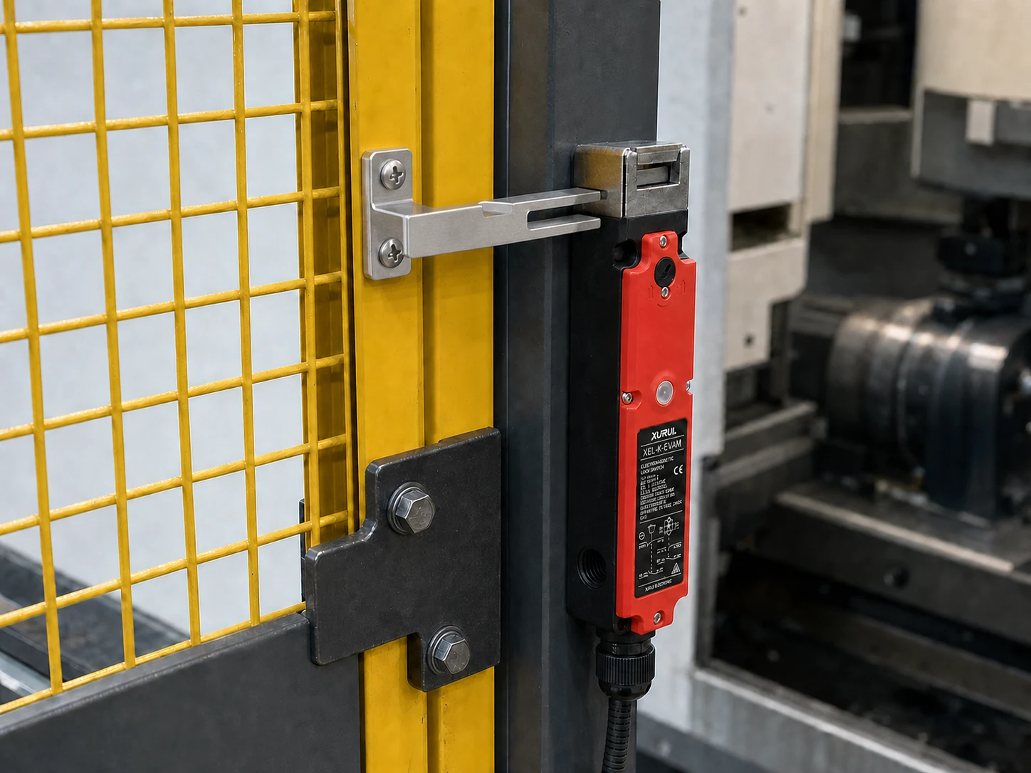
Choose a safety switch actuator by matching the exact switch series, guard motion, entry direction, and insertion depth before setting the door stop. An actuator that only looks compatible can damage the head or leave the guard signal unstable. ISO 14119:2024 covers the guard parts that actuate interlocking devices and measures that reduce foreseeable defeat.
This guide compares straight, angled, and flexible actuators, then covers installation, fault diagnosis, and retesting. It also shows why a shared key shape does not make two switch series compatible.
What Is a Safety Switch Actuator?
A safety switch actuator is the separate key or tongue mounted to a movable guard in a tongue-operated safety interlock. Closing the guard inserts the actuator into the switch head, which moves the internal mechanism and changes the monitored contact state. A guard locking model can hold the seated actuator until the safety system meets its release condition.
The actuator forms one part of the interlocking function. A separate latch or stop carries normal door loads. Actuator shape, mounting position, insertion path, and switch compatibility determine where the contacts change state. The function of a safety interlock switch is to detect guard position so the safety system can stop or inhibit hazardous motion when the guard opens.
Which Safety Switch Actuator Design Fits the Guard Movement?
The actuator design should follow the guard’s actual closing path. Use straight entry for repeatable linear movement and angled or flexible designs for offset or changing entry angles. The actuator must still belong to the approved switch family, even when another key has a similar shape.
Straight Actuators for Direct Entry
Use a straight actuator on a sliding, lift-off, or well-supported hinged guard when the key approaches the head on a repeatable line. The direct path reduces side load and makes insertion depth easier to measure. Door sag can still move the key toward the edge of the slot, so check the closed position across the guard’s full service range.
Angled Actuators for Offset Entry
The angled form moves the mounting face away from the key entry line when a frame, hinge, or narrow bracket blocks a straight mount. The angle must match the guard’s closed position and swing arc. Do not force an angled key into a straight slot to hide poor bracket positioning.
Flexible Actuators for Changing Entry Angles
As a hinged guard closes, a flexible actuator accepts limited angular change through the final part of the arc. This movement can reduce binding, but it does not correct loose hinges, frame movement, or uncontrolled impact. Compact safety interlock installations still need enough room for the specified operating radius and service access.
How Should Buyers Match and Install a Safety Switch Actuator?
Match the switch series first, then set the entry direction, insertion depth, and door stop from the manufacturer’s drawing. A similar key shape does not prove mechanical fit.
Matching the Exact Switch Series
Use only an actuator listed for the exact switch family. Similar tongues can differ in width, shoulder position, coding, travel, or lock engagement. An unapproved key can damage the switch head or change how the safety function responds when the guard closes.
Compare these items before approval:
- switch series and full ordering code
- actuator part number and mounting form
- guard type and closing path
- locking or non-locking function
- required contact state at the closed position
Checking Entry Direction and Insertion Depth
Check every allowed head entry direction on the manufacturer’s drawing, then use the direction that gives the actuator a clean approach. The closed guard must place the key inside the published operating or lock zone without bottoming out. Incomplete insertion can create intermittent contacts, while excess travel can load the key, head, or lock.
Mark the accepted closed position on the bracket during commissioning. Recheck the mark after seals settle and the hinges carry the full door weight. A hand test before final assembly can miss the resulting position shift.
Setting Mounting Clearance and a Separate Door Stop
Leave clearance for the key, switch head, cable, fasteners, and removal path. The actuator should enter without scraping the slot or pulling the switch body sideways. Use a separate latch or door stop to carry closing force. The safety switch body should not stop the moving guard.
Door weight, vibration, or compressed rubber cushions and seals can shift an inserted key outside the set zone. A separate stop keeps the actuator inside that zone and reduces damage or lock release problems. The stop must hold the guard without transferring continuous force into the actuator.
Applying the Selection Checks to XURUI Safety Switch Models
The XURUI safety interlock switch range includes XEL-S, XEL-K, XEL-B, and XD-MP5. Current XURUI model sheets list five key entry directions and 11 operating key options, including T-type, L-type, long, cushioned, adjustable, and multi-function forms. Listed codes include X-K1 through X-K6 and X-K8, with cushioned variants counted separately.
| XURUI series | Guard function | Actuator selection check |
|---|---|---|
| XEL-S | Compact guard locking | Check space around the compact body, key approach, and release mode |
| XEL-K | Guard locking with optional rear release | Match the entry direction, operating key, and rear access requirement |
| XEL-B | Guard locking with front or side emergency release options | Check key approach, release position, contact set, and control voltage |
| XD-MP5 | Mechanical guard position monitoring without electromagnetic locking | Match the operating key and direct-opening contact requirement, without assuming a holding-force function |
The XEL-K Series Safety Door Switch supports the full operating key set, but the final key should follow the drawing and guard motion:
- X-K1 is T-type, and X-K3 is long T-type.
- X-K2 is L-type, and X-K4 is long L-type.
- X-K5 adjusts horizontally. X-K6 adjusts horizontally and vertically.
- X-K8 is a hemispherical multi-function key.
Confirm the permitted angle range on the current drawing.
In the Xurui Switch product line, XEL models provide guard locking, while XD-MP5 monitors guard position without electromagnetic locking. Confirm the switch code, operating key, drawing, entry direction, and release method before engineering freezes the bill of materials. Choose XD-MP5 only where the risk assessment does not require the guard to remain locked.
What Causes Safety Switch Actuator Faults?
An intermittent guard input often begins with door movement, loose hardware, impact, wear, or debris at the key opening. Inspect the mechanical path before replacing the switch body.
| Fault source | What to inspect | Corrective action |
|---|---|---|
| Door sag or incomplete insertion | Rub marks, a changed door gap, or a key that recenters when a technician lifts the door | Correct the hinge, support, or bracket condition, then verify that the actuator reaches the specified operating or lock zone |
| Loose brackets or shifting position | Witness marks, elongated holes, cracked brackets, missing locking hardware, or incorrect fastener torque | Secure the approved hardware to the specified torque and replace any damaged mount |
| Impact, wear, or contamination | A bent tongue, a damaged head, metal chips, powder, oil residue, or dried cleaning residue inside the key opening | Clean by the manufacturer’s approved method and replace damaged actuator or switch components as specified |
Diagnosing Intermittent Guard Signals
Use the safety door switch selection and wiring guide to separate a mechanical entry fault from a contact, cable, or controller fault. Follow the site’s energy-control procedure before touching the guard or switch. Use controlled validation conditions for powered signal checks.
- Check the actuator part number against the switch series.
- Inspect the key, head, brackets, hinges, latch, and stop for movement or damage.
- During a controlled functional test, watch the door and lock inputs separately while closing the guard slowly.
- Compare the real insertion position with the manufacturer’s set zone.
- Check cable strain, terminals, and safety relay diagnostics if the mechanical path remains stable.
Do not hold a spare actuator in the switch to make the signal steady. That test separates the switch from the guard and can create an unsafe run condition.
Retesting the Guard Function After Adjustment or Replacement
A qualified person should retest every affected safety function before production resumes. Follow the approved validation procedure and keep people outside the hazard zone. Open the guard, confirm the expected stop or restart inhibit, then close the guard and verify stable door and lock states. Guard closure alone must not restart the machine.
Repeat the test at normal door speed for the cycle count required by the validation procedure. Record the actuator code, switch code, mounting position, fastener check, input states, and test result.
A changed actuator can affect the assumptions used for fault detection or guard locking. The final test should follow the machine risk assessment and the validation plan for the safety control system.
FAQ
Can a Safety Switch Actuator Be Replaced Without Replacing the Switch Body?
Yes. Maintenance can replace a safety switch actuator separately when the manufacturer lists the replacement for the exact switch series. Inspect the switch head, lock, and mounting before fitting the new key. A damaged head or enlarged slot can keep the new actuator from reaching a stable operating position.
Does a Safety Switch Actuator Determine the Holding Force of a Guard Locking Switch?
No, the rated holding force belongs to the complete guard locking switch design, not the actuator alone. The correct actuator must seat fully so the lock can reach its rated condition. A bent, incompatible, or partly inserted key can reduce real engagement even though the published switch rating stays unchanged.
Can a Bent or Worn Safety Switch Actuator Be Repaired and Reused?
No. Replace a bent, cracked, or worn actuator with the approved part. Straightening, welding, filing, or drilling can change its geometry and strength, causing binding, incomplete contact travel, or unreliable lock engagement.
Can a Spare Safety Switch Actuator Bypass a Guard Interlock?
Yes, a loose spare actuator can hold some tongue-operated switches in the closed state while the guard remains open. This bypass can let the machine receive a false closed-guard signal. Store spare keys under controlled maintenance access, and design the installation to reduce foreseeable defeat.
Can Changing a Safety Switch Actuator Affect PL or SIL Validation?
It can. A like-for-like replacement normally preserves the original design assumptions, but the safety function still needs a functional test. If the replacement changes geometry, coding, fault behavior, response time, or lock engagement, review the safety-function validation before restarting the machine. ISO 13849-1:2023 covers design and integration, ISO 13849-2:2012 covers validation, and IEC 62061:2021 with Amendments 1:2024 and 2:2026 covers safety-control design, integration, and validation.
XURUI Engineering Team






