
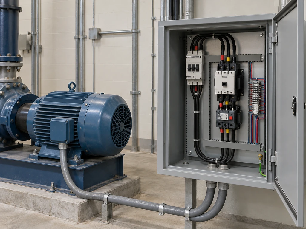
An FVNR motor starter connects a motor to full line voltage for starting and stopping. It runs the motor in one direction. The setup still needs to match the motor, load, supply, controls, and protection.
This guide explains how the power and control circuits work, what the starter components do, where FVNR starters are used, and what to specify before ordering.
What Does FVNR Mean in a Motor Starter?
FVNR stands for Full Voltage Non-Reversing. “Full voltage” means the motor receives line voltage at startup, without a reduced-voltage ramp or transition. “Non-reversing” means the starter does not change the motor’s direction. The term describes the starting method and direction; it does not specify the starter’s protection, disconnect, controls, or enclosure.
How Does an FVNR Motor Starter Work?
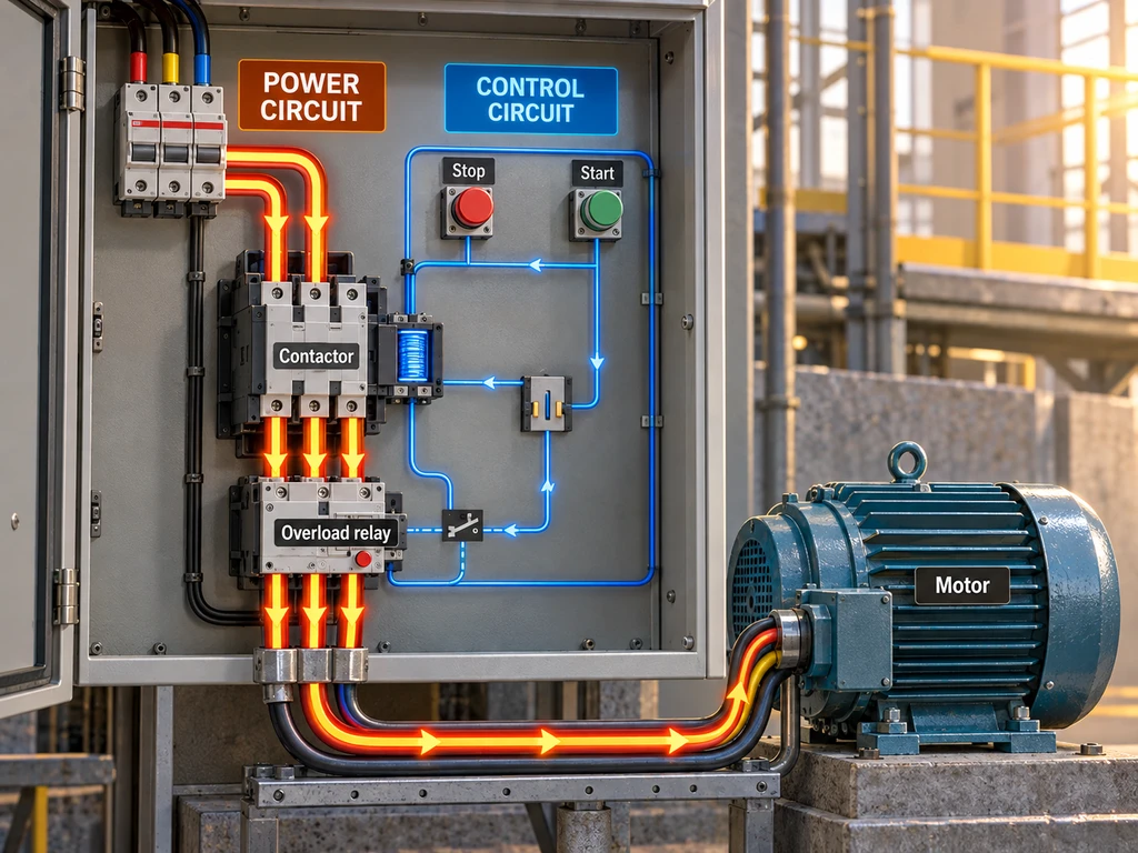
An FVNR starter has a power circuit that carries motor current and a control circuit that energizes the contactor coil. The control circuit sends commands to the contactor, whose main contacts switch power to the motor.
The Power Circuit
In a typical three-phase arrangement, incoming conductors pass through short-circuit protection and a disconnecting means, then through the contactor’s main contacts and the overload relay’s sensing elements before reaching the motor. Depending on the assembly, the disconnect and short-circuit protection may be built into the starter or installed elsewhere in the panel.
When the contactor closes, the motor receives full line voltage. Starting current is higher than normal running current and falls as the motor accelerates. Opening the contactor interrupts power to the motor.
The Control Circuit
The control circuit supplies the contactor coil through devices such as Start and Stop pushbuttons, a selector switch, or a controller output. When the coil energizes, the main contacts close. If the coil loses power, a spring opens them.
The overload relay’s trip contact is usually wired into the control circuit. If the relay trips, the contact opens, de-energizing the coil and stopping the motor. Normally open and normally closed describe a device’s contact position when unactuated: a conventional NC Stop contact opens when pressed, while an NO Start contact closes. Pilot switches use the same contact logic. If you want to learn more about how contact state affects a Start or Stop input, read this NO/NC switch guide.
Two-Wire and Three-Wire Control
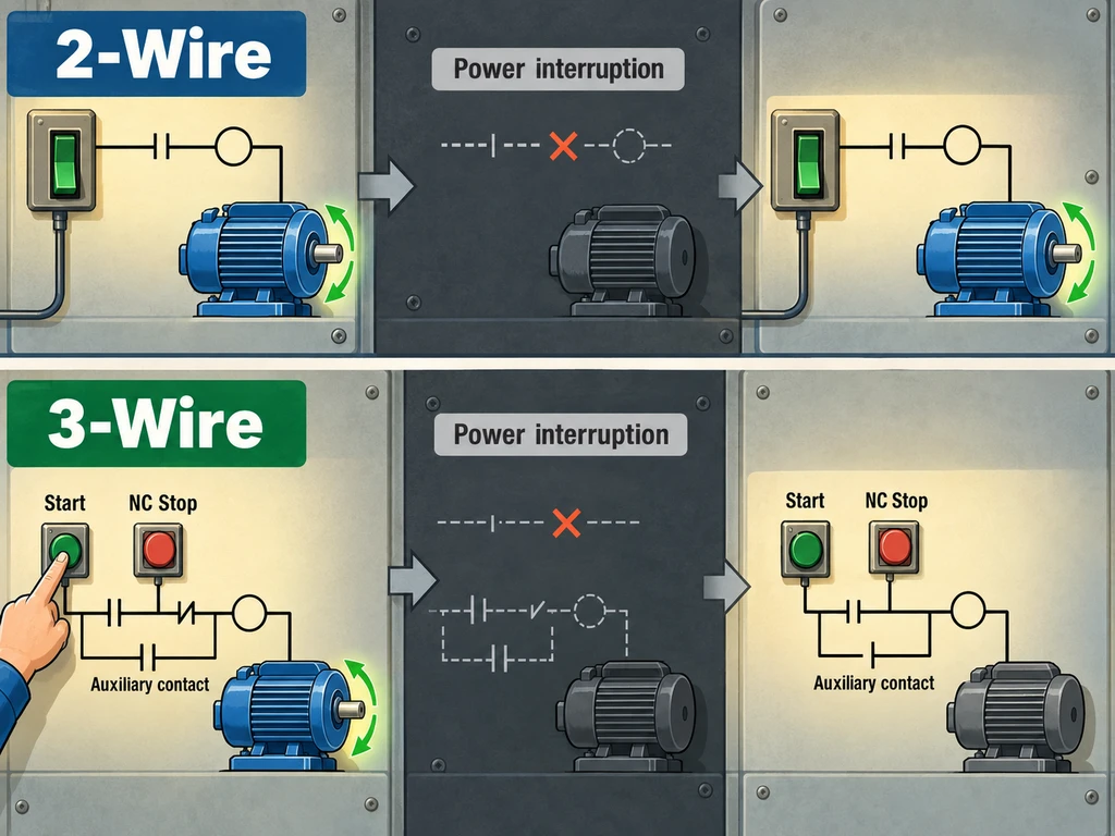
In two-wire control, a maintained contact or controller output commands the motor to run while closed and stops it when open. Three-wire control uses a momentary NO Start button, an NC Stop button, and a contactor auxiliary contact that keeps the coil energized after Start is released.
In a conventional circuit, a maintained two-wire run command can restart the motor when power returns if the command remains active. A three-wire seal-in circuit drops out after a power interruption and waits for a new Start command. Some two-wire circuits use a maintained toggle switch as the run command. Confirm that the selected model stays in position rather than springing back. If you want to learn more about reading a toggle-switch schematic and checking model specifications, read the toggle-switch schematic guide.
What Components Are in an FVNR Starter?
A typical FVNR assembly centers on the contactor and overload relay. Control devices, a disconnect, and short-circuit protection may come with the starter or be supplied separately in the panel.
Contactor and Coil
The contactor switches motor power. Its energized coil creates a magnetic field that pulls in the armature and closes the main contacts; a spring opens them when the coil de-energizes. Select a contactor rated for the motor voltage, load, and switching duty.
Overload Relay
The overload relay monitors motor current and trips when an overload lasts long enough to risk overheating. It typically opens a control-circuit contact, causing the contactor to drop out. Choose a relay with a current range that covers the motor’s nameplate current, then set it according to the motor data and relay instructions. An overload relay does not replace short-circuit protection.
Pilot Devices and Auxiliary Contacts
Pushbuttons, selector switches, and controller outputs send commands to the coil. Auxiliary contacts are linked to the contactor and can hold the coil on after a momentary Start command, provide interlocking, or report status. They carry control signals, not motor power.
Some panels use a toggle switch as a pilot input. Its contact arrangement and operating action should match the control scheme. For an example, the XT Series Toggle Switch comes in different configurations. Confirm that the exact model is rated for the control circuit; it does not replace the motor contactor.
Disconnecting Means
A disconnecting means isolates the supply for servicing. It may be a separate upstream device or part of a combination starter. The contactor’s open state is for normal motor control; it is not, by itself, a maintenance disconnect.
Short-Circuit Protection
A fuse or circuit breaker clears short-circuit faults. Contactors and overload relays are not designed to interrupt those faults, so they must be paired with suitable short-circuit protection.
For a U.S. control panel built to UL 508A, the panel’s SCCR must equal or exceed the available short-circuit current at the installation point. Determine the panel SCCR from the tested assembly or the UL 508A Supplement SB method. The specified protective device and component combination matter; a main circuit breaker’s interrupting rating alone does not establish the panel’s SCCR.
Where Are FVNR Starters Used?
FVNR starters are used with fixed-speed motors that run in one direction and can tolerate full-voltage starting. Pumps, fans, blowers, and compressor packages are common applications. The motor and load still need to accelerate within their normal operating limits.
Pumps and Water Systems
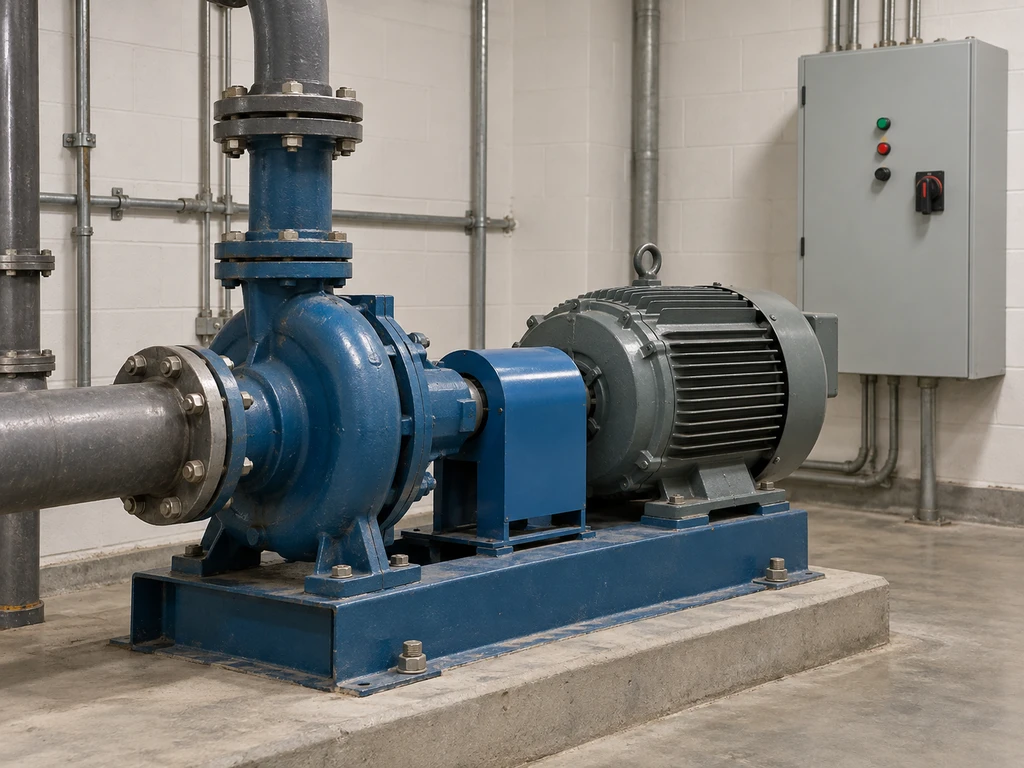
FVNR may be suitable for fixed-speed pumps used for water transfer or pressure service when the supply can support direct starting and the motor can accelerate the pump load. The starter provides on/off motor control; it does not adjust pump speed or regulate flow.
Fans and Blowers
Fixed-speed fans and blowers are common in ventilation systems. A large impeller can add enough inertia to lengthen acceleration, so confirm that the motor and starter can handle the normal starting time without nuisance overload trips. FVNR does not vary airflow through speed control.
Air Compressors
Fixed-speed compressor packages may use full-voltage starters, but the starting sequence matters. Check whether the package starts unloaded, how long the motor takes to accelerate, and how often it cycles. A loaded or repeated start can impose different torque and thermal demands than a normal start.
How OEMs and Panel Builders Can Specify an FVNR Motor Starter
Choose an FVNR starter by matching the motor and starting conditions first, then specify the controls, protection, and enclosure. The quote should identify the exact components and ratings included.
Check Motor and Supply Ratings
Read the motor nameplate for voltage, phase, frequency, horsepower, full-load current, and service factor. Match the supply and the starter’s published motor rating at the operating voltage. Horsepower alone is not enough: starting current, acceleration time, and expected start frequency also affect the application.
The overload relay’s range and setting must suit the motor. Branch-circuit short-circuit protection serves a separate function and must be coordinated with the starter assembly.
Select Starter Configuration and Enclosure
Choose an open starter mounted inside a control panel or a combination starter that includes the motor starter, disconnect, and short-circuit protection. Confirm that the configuration starts the motor in the required direction and at full voltage. If the application needs reversing or reduced-voltage starting, specify a different arrangement.
Select an enclosure for the installation conditions, including indoor or outdoor exposure, dust, moisture, washdown, and corrosive conditions. Check the enclosure’s stated rating and any temperature or ventilation limits that affect the installed components.
Confirm Control Voltage and Protection
Match the contactor coil voltage to the control supply, including any control transformer. Specify the control scheme and the auxiliary contacts needed for holding, interlocking, or status signals. Set the overload relay for the motor and its starting duty, then confirm the short-circuit protective device and assembly rating.
If the design uses a panel-mounted toggle as a control input, match its contact form and voltage and current ratings to the coil circuit. Once those requirements are clear, browse the toggle switch range to compare available pole and throw arrangements.
Compare Supplier Quotes and Documentation
Compare quotes against the same motor and panel requirements. Each quote should identify the starter and overload models, coil voltage, disconnect and short-circuit device, enclosure, auxiliary contacts, and assembly rating. Review the wiring diagram, datasheets, and applicable approval documents before releasing the bill of materials.
Final Checks Before Specifying an FVNR Starter
Trace a start command through both circuits: the control input should energize the coil, the main contacts should supply the motor, and an overload trip should open the control circuit. Confirm that the disconnect and short-circuit protection match the panel design, and that the motor’s behavior after a supply interruption matches the intended sequence.
If you want help checking whether a pilot switch fits the control circuit, send the pilot-switch specifications to XURUI, including its contact form, control-circuit voltage and current, operating action, panel cutout, and environment.
External Sources
- Understanding Electrical Starters
- How Do I Operate a Star Delta Starter with 2-Wire Control?
- CBRCI2 Series Prepackaged Full Voltage Starters
- Manual Motor Starter Guide
- Structure of a Motor Starter in Accordance with UL 508A
- Code Requirements for Short-Circuit Current Ratings






