Dielectric withstanding voltage (DWV) is the specified voltage an insulation path must withstand for a stated time without electrical breakdown. Hi-pot, short for high-potential, testing applies that voltage between parts that should remain electrically separated.
Insulation can block current during normal service yet contain a crack or narrow gap that fails under greater electrical stress. The test exposes such weaknesses without deliberately seeking the breakdown point.
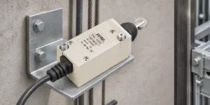
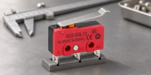
A switch can withstand a brief test voltage far above its operating rating without being suitable for switching a load at that voltage. The test checks insulation; the operating rating addresses actual circuit use. This article covers mechanical contact switches, including micro, limit, and toggle switches.
Key Electrical Terms for Switch Selection
These terms describe different limits. Substituting one for another can produce a switch that passes an insulation test yet cannot handle its intended load.
| Term | What It Indicates | Relevance to Switch Selection |
| Rated Operating Voltage | Voltage permitted under specified operating and load conditions | Evaluate together with current, load type, and AC/DC rating |
| Dielectric Withstanding Voltage | Insulation withstand at a specified voltage, duration, and test path | Compare only under equivalent test conditions |
| Insulation Resistance | Resistance measured across insulation at a specified DC voltage | Indicates resistance to current flow, without establishing high-voltage withstand |
| Breakdown Voltage | Voltage at which insulation fails under defined test conditions | Identifies a failure threshold, rather than an operating allowance |
For micro switch selection, the load rating determines what the contacts may carry and interrupt. A high DWV value cannot compensate for an inadequate DC or inductive-load rating.
How to Read a Switch’s Dielectric Withstand Specification
A useful specification identifies both the electrical stress and the insulation path exposed to it. Its voltage figure becomes meaningful only when the remaining conditions are known.

Test Voltage, Waveform, and Frequency
The specification distinguishes AC from DC and, for AC, identifies frequency and whether the value is root mean square (RMS) or peak. RMS expresses the effective AC voltage.
For example, OMRON’s D2SW-3 data, for models fitted with the specified insulating separator, lists 1,000 VAC at 50/60 Hz between terminals of the same polarity. This is a manufacturer example for that family, not a universal switch requirement. AC and DC substitution needs authorization in the governing test procedure; matching voltage numbers does not establish equivalent tests.
Test Duration
Duration normally describes the dwell, or time held at the specified voltage, separately from ramp-up. The cited D2SW-3 test holds voltage for one minute. A shorter production screen cannot automatically replace that test: its voltage and duration need their own documented basis.
Test Points
Typical paths include open contacts, separate circuits, and terminals to non-current-carrying metal. A double-pole contact arrangement introduces insulation between two switching circuits, so the test plan must address the specified paths between them.
The D2SW-3 specification illustrates the distinction: it lists 1,500 VAC between terminals and non-current-carrying metal, compared with 1,000 VAC between same-pole terminals. Testing one path does not establish another path’s performance.
Switch Position During Testing
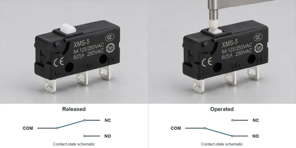
The COM, NO, and NC contact states determine which contact gap is open. COM means common, NO means normally open, and NC means normally closed.
On a conventional spring-return changeover switch, COM to NO is open when released; COM to NC opens when operated. Applying a contact-gap test across closed contacts creates a conductive path instead of stressing the intended insulation. The test plan therefore specifies both terminal pairs and actuator positions.
Pass and Fail Criteria
A pass requires the specified voltage and duration without prohibited breakdown or discharge, plus any stipulated current limit and subsequent checks. Completing the timer at an insufficient voltage does not establish compliance.
Test-current thresholds belong to the defined test procedure. A normal-operation leakage-current limit cannot simply be reused at the much higher dielectric test voltage.
Test Conditions and Footnotes
Footnotes can restrict a rating to a particular assembly or test stage. OMRON labels the cited D2SW characteristics as initial values. They do not automatically describe the switch after endurance testing or environmental exposure.
Environmental history matters too. For sealed micro switches, protection depends on the actuator seal, housing, and cable or terminal construction. A dry initial measurement does not establish performance after moisture conditioning. The specification should identify whether conditioning precedes the test.
How Hi-Pot Testing Is Performed on Switches
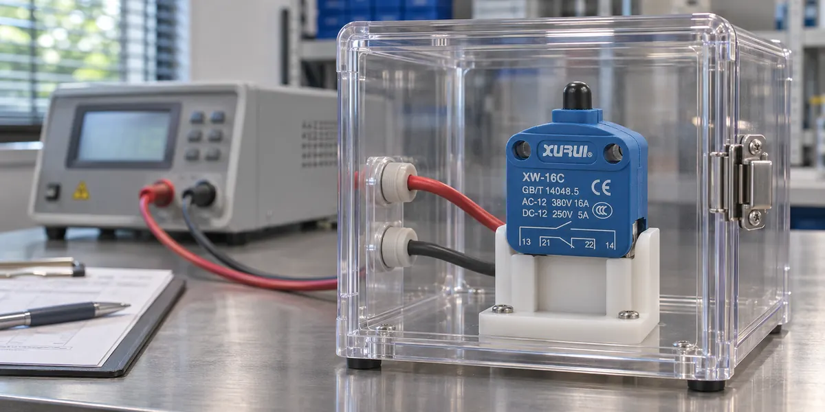
Hipot testing for switches uses a controlled high-voltage source and a defined connection sequence. Trained personnel should perform it at a guarded test station with suitable interlocks.

Step1: Confirm the Test Requirements
Identify whether the task is design qualification, production screening, or an authorized retest. Use the exact model’s test procedure to establish voltage, waveform, frequency, dwell, connections, actuator positions, conditioning, and failure criteria.
Record the referenced product standard and edition where the procedure invokes one. A general formula derived from operating voltage cannot replace these details: insulation paths and test purposes may differ even within one switch family.
Step2: Prepare the Switch and Test Connections
Disconnect the switch from its normal power supply and external circuits. Inspect the sample, fixture, and high-voltage leads. Confirm contact states with a low-voltage continuity check before applying high voltage.
Connect the tester’s high-voltage output and return to the designated points. Follow its grounding instructions and verify the guard interlock. For illuminated or electronic variants, use their specific connection procedure to avoid stressing unintended components.
Step3: Apply the Specified Test Voltage
Run the prescribed voltage ramp and dwell while monitoring actual voltage, test current, and discharge indications. Confirm that the source maintains the required voltage under load; the programmed setpoint alone is insufficient evidence.
Stop and investigate an abnormal result. Do not change voltage, timing, or trip settings during an acceptance test merely to obtain a pass. Such changes would alter the test being performed.
Step4: Safely End the Test and Record the Results
Complete the prescribed shutdown and discharge sequence. Confirm that hazardous voltage has been removed before accessing the fixture, particularly after DC testing, which can leave stored charge.
Perform any required visual or functional checks. Record sample identification, equipment identification, connections, actuator position, actual test conditions, and outcome. Retain the original failure record when further investigation or retesting follows.
Common Causes of Hi-Pot Test Failures in Switches
Genuine failures arise when an insulation path cannot sustain the imposed electric field. Cracks can shorten the effective barrier, while moisture, contamination, or conductive debris can create surface paths. Insufficient clearance, the shortest distance through air, can permit sparkover. Creepage distance follows the insulating surface, where contamination can support flashover.
An alarm can also originate outside the switch. Closely spaced fixture terminals, damaged leads, and contamination on the test fixture may discharge first. Locating the discharge distinguishes a product defect from a setup defect.

Current trips require similar care. AC testing draws capacitive current even through sound insulation. During DC ramp-up, charging current rises with the rate of voltage increase. Either can exceed an unsuitable trip setting without proving breakdown. Locating the discharge or examining current behavior helps distinguish an insulation defect from a measurement problem. Any setting change needs support from the approved procedure and the investigation; a required current limit remains binding.
For a model-specific review, discuss your switch specifications with XURUI and share the load, contact arrangement, and required dielectric test conditions.
Frequently Asked Questions
Can a Multimeter Replace a Hi-Pot Tester?
No. An ordinary multimeter can identify open and closed contacts or gross shorts, but it does not apply the required dielectric test voltage. Insulation may appear open at the meter’s low voltage and fail under a much stronger electric field. Even a dedicated insulation-resistance meter serves a different test purpose.
Can Repeated Hi-Pot Testing Damage a Switch?
It can, particularly with excessive voltage, prolonged application, or repeated discharges through defective insulation. Damage depends on the insulation and the tester’s available current and stored energy. A prescribed withstand test aims to leave sound insulation intact, but that does not justify unlimited repetition. Retesting should follow the defined investigation and acceptance procedure rather than continue until a failed sample passes.
Does Passing a Hi-Pot Test Guarantee a Switch’s Electrical Life?
No. Electrical life measures switching endurance under stated load conditions. Contact erosion, welding, and increasing resistance develop through operating cycles, and contact material selection affects those mechanisms. A switch may have adequate insulation yet wear rapidly under excessive inrush or an unsuitable load. Electrical-life evidence must therefore match the intended voltage, current, load type, and switching duty.
External Sources
- MIL-STD-202 Method 301, Dielectric Withstanding Voltage
- OMRON D2SW Sealed Subminiature Basic Switch Datasheet
- The Dielectric Voltage Withstand Test (UL)
- Does Repeating the Hipot Test Damage Your Cable? (Cirris)
- Dielectric Withstand Test Guide (Vitrek)