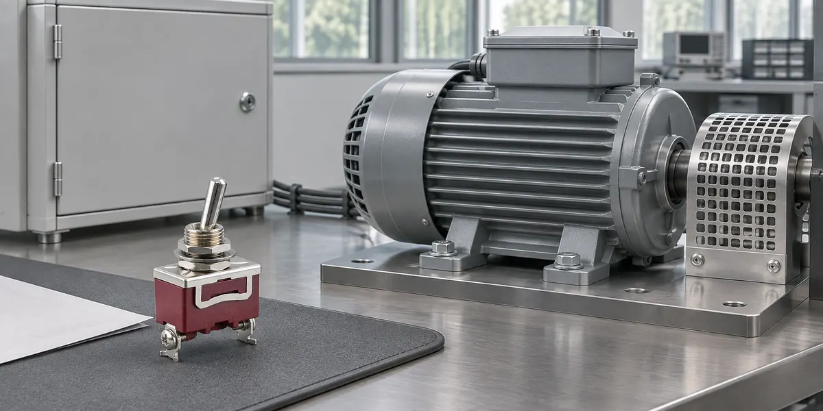
Motor inrush current stresses switch and relay contacts far beyond what full-load amps indicate. Reliable device selection accounts for startup current, continuous running, and circuit interruption. Checking motor FLA against a general switch rating does not establish compatibility.
Direct-on-line AC induction motor starts illustrate the electrical demands placed on mechanical switches and electromechanical relays. Solid-state relays require separate semiconductor and thermal evaluations.
Why Full-Load Amps Do Not Describe Motor Startup
Full-load amps describe steady-state operation at rated mechanical output. During acceleration, the motor draws current along a completely different profile.
Full-Load Amps
Full-load amps (FLA) define the current drawn when a motor delivers rated output under specified voltage and frequency. Multi-voltage motors list separate FLA values for each wiring configuration. Operating current varies with mechanical load. A lightly loaded motor draws less than nameplate FLA. However, running current measurements and nameplate values provide no data on peak inrush amplitude or acceleration duration.
Startup Current Profile
Direct-started induction motors draw peak current at standstill, which decreases toward running levels as the rotor accelerates. The starting sequence involves an initial transient spike followed by elevated current throughout acceleration. Locked-rotor amps (LRA) reflect standstill demand under rated conditions, but they do not describe the complete waveform. Similarly, instantaneous peak current must be evaluated separately from RMS ratings to ensure consistent comparisons.

Universal multipliers cannot account for these variations. Motor design and starting methods determine current magnitude, while load inertia and supply stability govern acceleration time. Establishing an accurate profile requires manufacturer data or physical measurement.
Which Ratings Determine Motor Switching Capability?
Proper device selection depends on ratings matching the electrical supply, load characteristics, and operating duty. A certified motor rating accounts for defined starting conditions. Applying arbitrary multipliers to FLA yields inaccurate hardware ratings.
Load-Specific Ratings
A resistive rating verifies performance strictly under resistive test parameters, providing no assurance of motor-switching capability. The distinction between inductive and resistive loads is critical. Motor startup surges and stored magnetic energy impose severe stresses on contacts, requiring careful review even for general inductive-load ratings.

Switches require verified motor ratings at the operating voltage, such as a horsepower rating or a certified motor-load current limit. For contactors, utilization categories define intended switching duty. Category AC-3 covers starting squirrel-cage motors and disconnecting them during normal running. It does not certify devices for repeated current interruption during acceleration.
Contact Current Ratings
Contact specifications divide performance into three distinct electrical functions:
- Making capability defines performance during contact closure, including handling startup inrush current.
- Carry current defines continuous conduction through closed contacts within allowable thermal limits.
- Breaking capability defines circuit interruption at specified voltage and load levels.
Continuous carry capacity does not equal switching capacity. Opening an inductive circuit generates transient voltages and sustained electrical arcs across parting contacts. Direct current lacks the periodic zero-crossings that naturally quench AC arcs, preventing the transfer of AC ratings to DC circuits.
Conversely, a motor startup surge above a device’s continuous current limit does not automatically disqualify it. Documented motor ratings account for this short-duration starting profile.
Electrical Life
Electrical life measures contact endurance under specific electrical loads and test conditions, while mechanical life reflects no-load mechanism cycling. Endurance evaluations require ratings matching actual operating voltage, load characteristics, and cycle frequency. High mechanical cycle ratings provide no proof of durability under motor-starting stresses.
Frequent cycling, extended acceleration, and high-current interruption escalate contact wear. Data derived from lighter loads or benign disconnection conditions cannot predict operational lifespan on a motor load.
How to Check a Switch or Relay Against the Motor Load
Evaluating a switch or relay requires establishing the operational duty, matching parameters against documented ratings, and validating performance in the final enclosure. Circuit configurations and terminal styles narrow candidate selections for panel-mounted toggle switches, but documented electrical ratings determine ultimate suitability.
Defining the Actual Switching Duty
Evaluating the application starts with logging exact contact duty requirements:
- Motor voltage, supply type (AC or DC), phase count, frequency, rated power, and FLA.
- Starting method, startup current waveform, and acceleration time.
- Operating frequency (starts per hour) and required service life.
- Normal shutdown conditions, alongside duty requirements like jogging, reversing, or aborting starts during acceleration.
Determine whether the contacts carry primary motor current or switch a contactor coil. In electrical motor control circuits, manual switches often handle control signals while contactors manage heavy motor current. When switching a coil, select contacts based on coil pickup, holding, and turn-off characteristics. Motor FLA has no bearing on pilot-duty control contacts.
Matching the Duty to Published Ratings
Evaluate application parameters against the complete part number rather than the broad series name. For instance, the XT Series toggle switch includes multiple circuit and terminal configurations that alter published ratings.
Classify each requirement as supported, exceeded, or undocumented. Exceeding any limit disqualifies the device, while undocumented parameters require manufacturer confirmation. For electromechanical relays, evaluate coil drive specifications and contact ratings separately.
Verifying Application Suitability
Confirm that enclosure conditions remain within rated limits. Measure local operating temperature, inspect terminal connections, and apply manufacturer derating where necessary. Capture startup current across representative load and supply conditions using waveform-capable instrumentation. Monitor relay coil voltage during motor starts to ensure voltage dips do not disrupt contact performance.
Inspect contacts for temperature rise, sticking, release failure, and increased resistance over a defined cycle count. Short trials confirm immediate operation, but they do not establish long-term electrical endurance.

Can a 10A Relay Switch a Motor With an 8A FLA?
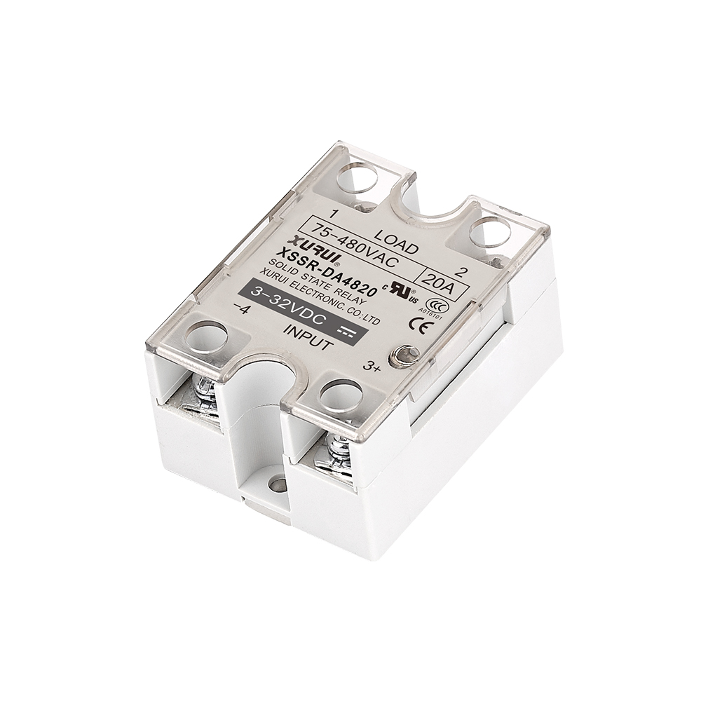
A 10A relay can switch an 8A FLA motor only if documented ratings certify it for that specific motor duty. A 10A resistive rating provides no such confirmation. Evaluating a 230V AC, single-phase motor with an 8A FLA demonstrates the limitation of general ratings when startup profiles remain unverified.
| Known Motor Data | Required Rating Evidence | Selection Decision |
| 230V AC, single-phase supply | Contact rating for that voltage and motor load | A different voltage or DC-only rating does not qualify the relay |
| 8A FLA; relay lists 10A resistive only | Applicable motor rating and startup conditions | Motor suitability remains unconfirmed |
| Startup current and duration unknown | Motor starting data or measured profile matched to permitted duty | Obtain the missing data before approving |
| Required starting frequency and life defined | Electrical endurance and permitted operation frequency | Select only when documented conditions cover the requirement |
| Candidate has a suitable motor rating | Matching supply, startup, stopping, and installation conditions | Proceed to application verification |

A properly rated motor relay should not be dismissed simply when startup current exceeds 10A; qualified motor ratings often account for high inrush over brief intervals. Conversely, specifying a higher general-purpose current rating does not resolve load mismatches. This principle applies directly to a heavy duty toggle switch’s current rating: nominal amp values must always be evaluated alongside operating voltage, load characteristics, and switching duty.
What to Confirm Before Ordering a Switch or Relay
Procurement requires confirming that the final bill-of-materials matches evaluated hardware, supported by complete technical documentation.
Verify the following details with the component supplier:
- The complete part number, including contact arrangement, coil voltage where applicable, and terminal suffixes.
- A current datasheet showing applicable load ratings and operating limits.
- Approval or certification documents covering the exact model and destination market.
- Samples matching the proposed production configuration, alongside agreed test and acceptance criteria.
- Confirmation of order configuration, quantity, delivery lead time, and part-substitution policies.
Document and resolve any open technical questions before placing an order. A family-level catalog or certification logo does not validate electrical ratings or compliance for every part variation.
To discuss operating conditions with XURUI, submit the proposed model, system voltage, motor FLA, startup profile, and cycling frequency. These data points allow engineering to identify relevant documentation and assess compatibility.
External Sources
- ABB — How to Read a NEMA Motor Nameplate
- Megger — Motor Inrush Current
- OMRON — Precautions for Correct Use of Basic Switches
- OMRON — General Purpose Relay Terms
- Schneider Electric — AC-1 and AC-3 Utilization Categories
- Panasonic Industry — Relays Cautions for Use