A subminiature micro switch must match both the electrical circuit and the mechanism that operates it. A replacement can fit the mounting holes yet switch at the wrong position, require too much force, or wear quickly under the actual load.
Reliable selection starts with those interfaces. The same checks also establish whether an alternative is a direct replacement or requires changes to the equipment.
What Is a Subminiature Micro Switch?
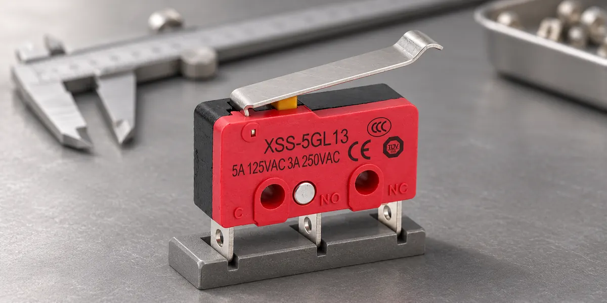
A subminiature micro switch is a compact electromechanical switch that changes contact state through a snap-action mechanism. Movement of a plunger or lever loads an internal spring. Once the mechanism passes its switching point, the spring moves the contacts rapidly.
That action allows a slowly moving door, cam, or linkage to produce a distinct electrical transition. It does not eliminate contact bounce, which is the brief repeated opening and closing that can accompany contact movement.
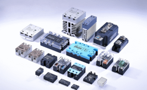
Within micro switch families, size, actuator, terminal, and load options serve different installation needs. The term “subminiature” alone establishes neither an interchangeable footprint nor a current rating. The drawing and complete part number identify the actual configuration.
Key Subminiature Micro Switch Specifications
A useful specification describes a value and the conditions under which it applies. Electrical ratings depend on voltage and load type; mechanical dimensions depend on their measurement reference and tolerances.
| Specification | What to Check | Why It Matters |
| Body and mounting | Maximum dimensions, hole locations, clearances | Determines whether the assembly fits |
| Terminals | Type, dimensions, spacing, orientation | Determines connection and board compatibility |
| Contact configuration | Normally open, normally closed, or changeover | Establishes circuit behavior |
| Electrical rating | Voltage, AC/DC, load type, inrush | Determines switching suitability |
| Minimum applicable load | Specified voltage/current conditions | Indicates suitability for small signals |
| Operating and release force | Limits and measurement location | Determines actuation and return behavior |
| Operating position | Reference surface and tolerance | Determines where switching occurs |
| Travel | Pretravel, overtravel, differential travel | Establishes movement and reset requirements |
| Endurance | Electrical/mechanical cycles and test conditions | Connects service life to actual duty |
| Environment and approvals | Temperature, protection, exact approved variant | Defines application and documentation limits |
Pretravel is movement before operation. Overtravel is movement beyond the operating position. Differential travel is the distance between operating and release positions.
These quantities work together. A mechanism must move far enough to switch reliably and then return far enough to reset. An overtravel value marked “minimum” describes guaranteed available movement; it does not establish a universal maximum permissible stroke.

How to Select a Subminiature Micro Switch
For a new design, start with the circuit and required movement. These establish the electrical and mechanical limits before environmental protection narrows the choice.
Electrical Load
The starting choice is a switch rated for the actual voltage, current, and load type. Alternating current (AC) and direct current (DC) ratings are distinct. AC current periodically crosses zero, helping extinguish an arc between opening contacts; DC lacks that assistance.
Steady current also tells only part of the story. A motor can draw substantially more current during startup, while an inductive load can produce a voltage surge when interrupted. A resistive rating alone does not establish suitability for either condition.
For small signals, contact material selection affects reliability. Surface films can prevent dependable conduction at low voltage and current. Gold contact options are commonly offered for such service, but the stated minimum applicable load and actual operating conditions remain decisive.
Mechanical Fit and Actuation
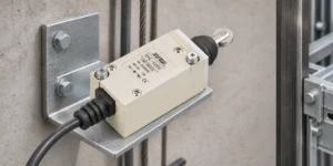
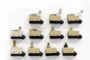
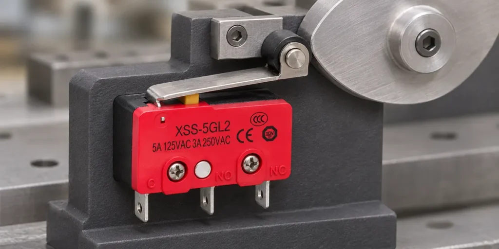
A pin plunger suits controlled pressure along its intended axis. A roller lever suits a moving surface that passes across the actuator. Different actuator types change the force and movement needed to switch.
Lever length also changes mechanical advantage. A longer lever can reduce force at the contact point while requiring more movement. Force values measured at different lever positions therefore cannot be compared directly.
The mechanism needs room for the entire stroke, including dimensional variation between parts. Its final position should provide reliable operation without forcing the actuator beyond its permitted travel or using the switch as a mechanical stop.
Operating Environment
An unsealed switch may suit a protected, dry enclosure. Exposure to droplets or contamination can justify sealed construction, provided its temperature limits and materials also suit the application.
Waterproof switch construction includes the actuator seal, housing joints, and terminal or cable exit. Protection at the body does not automatically protect an exposed connector. Likewise, an ingress protection rating does not establish resistance to cleaning chemicals or oils. Those exposures require separate material and assembly evidence.

How to Verify a Direct Replacement
A direct replacement preserves the equipment’s installation interfaces and required behavior without modifying its mounting, connections, or operating mechanism. A suitable alternative may still require modifications, which should be identified explicitly.
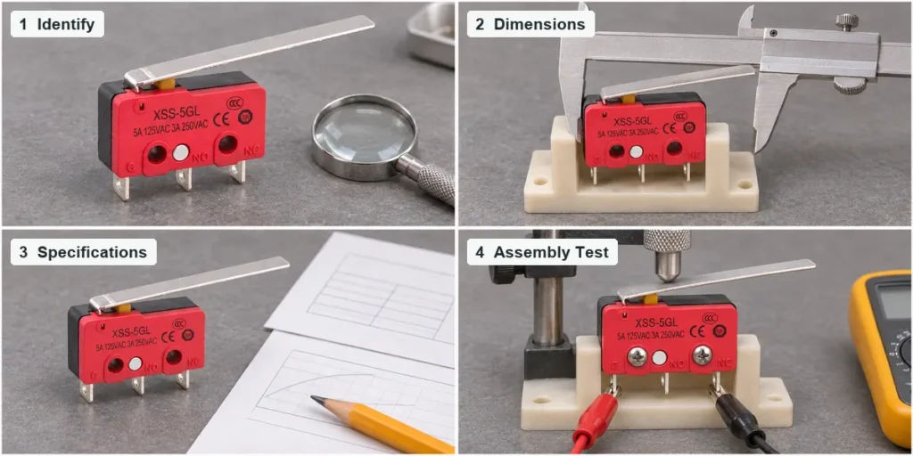
Step1: Identify the Original Switch
Record the complete part number, including suffixes. Photograph the markings, actuator, terminals, and installed position before removal. Record the circuit voltage, load, switching frequency, and environmental exposure.
If the part number is unreadable, measure the accessible mounting and connection features and document the mechanism’s movement. Treat these observations as a starting specification. A broken lever or worn contact cannot establish the original operating force or electrical rating.
Obtain an original drawing or equipment specification where available. It provides a sounder reference than measurements taken only from a damaged component.
Step2: Compare Dimensions and Terminal Layout
Compare the candidate drawing against the original mounting interface. Include hole diameters and locations, body clearance, actuator envelope, and terminal dimensions. For a printed circuit board (PCB), compare pin spacing, thickness, bend direction, and insertion depth.
Then compare terminal functions. On a single-pole double-throw (SPDT) switch, the common terminal (COM) connects to the normally closed terminal (NC) when unactuated and transfers to the normally open terminal (NO) when operated.
COM, NO, and NC wiring depends on those functions, not the apparent order of the pins. Do not assume that similar housings use identical terminal assignments.
Step3: Compare Ratings and Operating Conditions
Create a comparison against the application requirements, recording each candidate value and its source. Check the electrical rating at the required voltage and load type, together with minimum-load suitability and electrical endurance.
Compare operating and release forces at the same specified contact point. Compare operating positions from a common reference, such as the mounting-hole center or body base. Include tolerances: matching nominal positions can conceal a difference large enough to prevent reliable operation.
Check temperature limits, sealing, and the required documentation for the exact variant. Where an equipment approval specifies particular component ratings or approvals, identify those conditions before accepting a substitute. A family-level approval statement does not establish coverage of every suffix.
Step4: Validate the Replacement in the Assembly
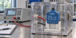
Disconnect power before installation and continuity testing. Isolate the switch electrically where parallel circuit paths could affect the reading. Confirm contact states before and after actuation.
Install the candidate using its specified mounting and connection instructions. Move the mechanism through its full operating range. Check reliable operation, release, clearance, and travel margin at the relevant dimensional extremes. Do not accept an audible click as proof of correct electrical switching.
Test the assembled equipment under its intended load and operating conditions. For electronic inputs, check that contact bounce does not produce unwanted commands. Where endurance matters, use supporting test evidence or a qualification test representing the required duty.
A successful continuity check establishes basic function. It cannot establish long-term performance.
Common Subminiature Micro Switch Replacement Mistakes
Several shortcuts turn a plausible substitute into an unreliable repair:
- Choosing by appearance. Similar bodies can conceal different mounting references, pin layouts, or operating positions.
- Treating a higher current rating as an upgrade. A power-switching contact may perform poorly with a small signal if its minimum-load characteristics are unsuitable.
- Bending terminals or changing levers to obtain a fit. Such changes can stress the housing or alter actuation, so the modified assembly needs its own evaluation.
- Using mechanical endurance as electrical life. Unloaded cycling does not reproduce contact wear from switching the application’s load.
- Validating only one convenient operating condition. A sample that works at room temperature may behave differently at the mechanism’s tolerance limits or under the actual electrical duty.
The purpose of replacement testing is to expose these differences before the equipment returns to service.
Get Help Selecting a Compatible Replacement
For an XURUI replacement review, submit your switch specifications with the original model, photos or drawing, electrical load, actuator movement, environment, and quantity. These details support a candidate shortlist for compatibility testing.
External Sources
- OMRON Basic Switches Technical Overview
- Honeywell ZM and ZM1 Subminiature Switch Datasheet
- OMRON Basic Switch Safety Precautions
- OMRON Precautions for Correct Use of Basic Switches
- ARATAS Minimum Applicable Load and Contact Failure
- ARATAS General Application of Switches