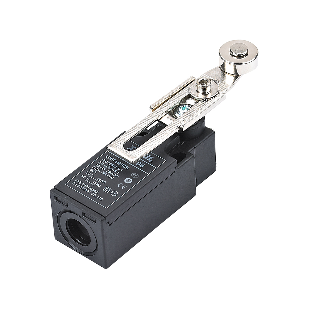
Control cabinet technicians frequently encounter erratic machine stops caused by misidentified switch terminals or inverted logic states. In industrial machinery, wiring a basic snap-action switch requires a precise understanding of contact transfer points under mechanical actuation.
This guide explains standard micro switch wiring across common (COM), normally open (NO), and normally closed (NC) terminals. It details multimeter testing procedures, control circuit topologies, programmable logic controller (PLC) digital input connections, and enclosure selection criteria for industrial machinery.
How COM, NO, and NC Terminals Function in a Micro Switch
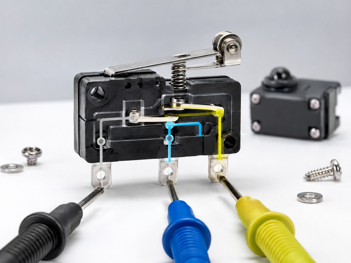
A standard micro switch operates on a single pole double throw (SPDT) contact mechanism that routes an incoming electrical signal through one of two distinct paths. The common (COM) terminal serves as the electrical input where power or logic voltage enters the switch assembly. The normally closed (NC) terminal maintains continuous electrical contact with COM while the switch rests in its unactuated state. In contrast, the normally open (NO) terminal remains disconnected from COM until an external mechanical force depresses the switch plunger or lever.
Inside the switch housing, an internal leaf spring maintains contact pressure between the movable contact arm and the stationary NC contact. When external mechanical force depresses the actuator to its operating point, the internal snap-action mechanism snaps the movable contact away from NC and transfers it to NO within milliseconds. This rapid snap action occurs independently of the external actuator speed, which helps suppress contact arcing, ensures clean signal transitions, and prevents contact chatter under continuous industrial operation.
Verifying Terminal Continuity With a Multimeter
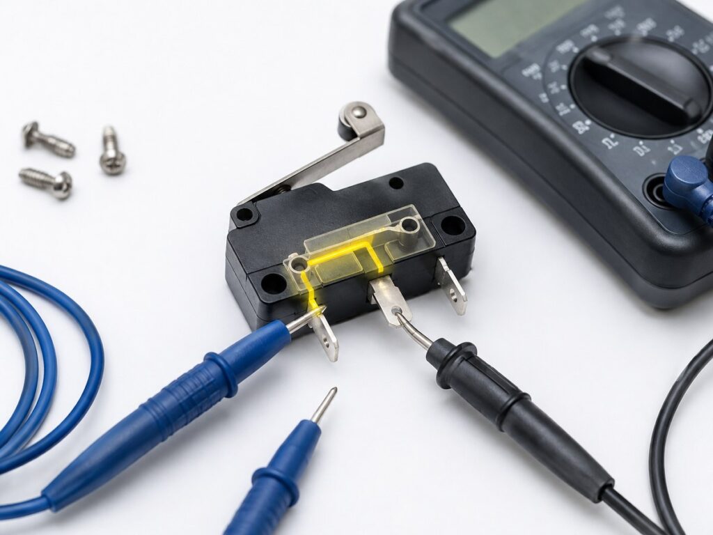
Before connecting field wiring or powering a control circuit, verify terminal assignments with a digital multimeter set to resistance or continuity mode. Stamped terminal markings on molded phenolic or thermoplastic switch cases can wear off or become obscured inside crowded junction boxes.
| Terminal Pair | Unactuated State | Actuated State | Expected Multimeter Reading |
|---|---|---|---|
| COM to NC | Closed circuit | Open circuit | Zero to 0.5 ohms unactuated, infinite resistance (OL) actuated |
| COM to NO | Open circuit | Closed circuit | Infinite resistance (OL) unactuated, zero to 0.5 ohms actuated |
| NO to NC | Open circuit | Open circuit | Infinite resistance (OL) in both unactuated and actuated states |
Testing the Normally Closed Contact Path
Connect the black multimeter probe to the COM terminal and the red probe to the NC terminal. With the actuator untouched, the meter must display continuity with near-zero electrical resistance, typically below 0.5 ohms for clean contacts. Next, depress the actuator plunger until you hear the distinct mechanical click. The meter display must instantly change to open loop (OL) or infinite resistance, confirming that the contact set breaks cleanly when actuated.
Testing the Normally Open Contact Path
Move the red meter probe from the NC terminal to the NO terminal while keeping the black probe on the COM terminal. In the unactuated state, the meter must register an open circuit with no continuity tone and an infinite resistance reading. Depress the actuator plunger to its full stroke. The meter must immediately indicate continuity and low resistance, confirming that the contact set closes reliably under mechanical actuation.
Connecting Micro Switches in Industrial Control Circuits
Industrial control schemes use micro switches as position sensors, safety gates, and operator triggers. Choosing between NO, NC, or dual-state wiring depends on whether the control system requires active-high signals, fail-safe trip circuits, or positive status verification.
Normally Open Wiring for Start and Trigger Signals
Wire the line voltage or positive DC supply conductor to the COM terminal, then route the return conductor from the NO terminal to the relay coil, indicator lamp, or input module. In this normally open configuration, no current flows while the mechanism remains at rest. When a passing machine part depresses the actuator, the internal contact closes the circuit to trigger an operational sequence, count parts, or start a downstream conveyor.
Normally Closed Wiring for Safety and Travel Limits
Understanding normally open versus normally closed contacts is essential for travel limits, where current must flow continuously through the switch during normal machine travel. When a machine carriage exceeds its allowable boundary and strikes the switch arm, the contact snaps open, immediately breaking current flow to the motor starter coil or safety relay. If a control wire breaks, loosens from its terminal, or suffers physical damage, the circuit drops out instantly, preventing dangerous overrun.
Changeover Wiring for Dual State Feedback
Certain industrial automation processes require positive confirmation of both resting and tripped conditions. By connecting COM to a common DC source, NC to an idle-status input, and NO to an active-trip input, a single SPDT micro switch provides continuous two-wire telemetry. If both inputs register high or both register low simultaneously, the supervisory controller flags an electrical fault or mechanical switch failure before machine operation resumes.
Series and Parallel Micro Switch Configurations
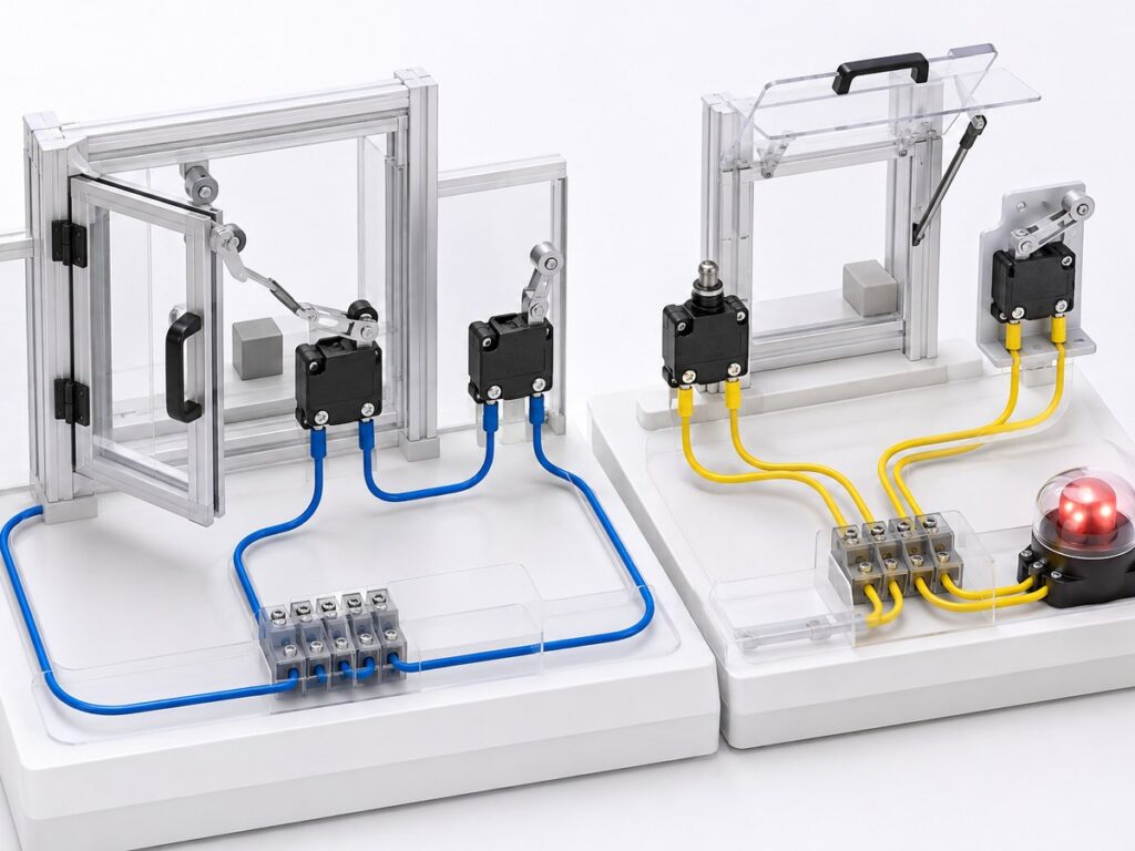
Multi-switch arrangements allow machinery builders to monitor multiple inspection points or access doors with coordinated logic strings. Wiring switches in series or parallel dictates how the control system responds to simultaneous or sequential switch activations.
Series Strings for Multi-Point Safety Interruption
Wiring multiple NC micro switches in series creates a hardwired AND logic chain where every guard door must remain closed for machine power to engage. If any single door opens or any mechanical switch trips along the chain, the continuous loop breaks and halts machine motion. However, machine designers must account for fault masking in long series strings, where an unnoticed contact weld on one switch can remain undetected if other switches in the loop continue to cycle normally.
Parallel Connections for Alternative Status Triggers
Wiring multiple NO micro switches in parallel creates a hardwired OR logic arrangement where actuation at any single point triggers the output. This layout suits warning annunciators, automated bin-fill indicators, and emergency pull-wire bypass stations where any trip signal must initiate an alarm. Parallel connections must not serve as primary safety stops because a severed conductor disables that individual detection point without giving prior warning to machine operators.
Wiring a Micro Switch to a PLC Digital Input
Much like conveyor safety switch wiring, automated machinery interfaces field micro switches directly with programmable logic controller digital input modules. Matching the switch contact wiring to the input module circuit architecture ensures clean signal detection and prevents electrical damage.
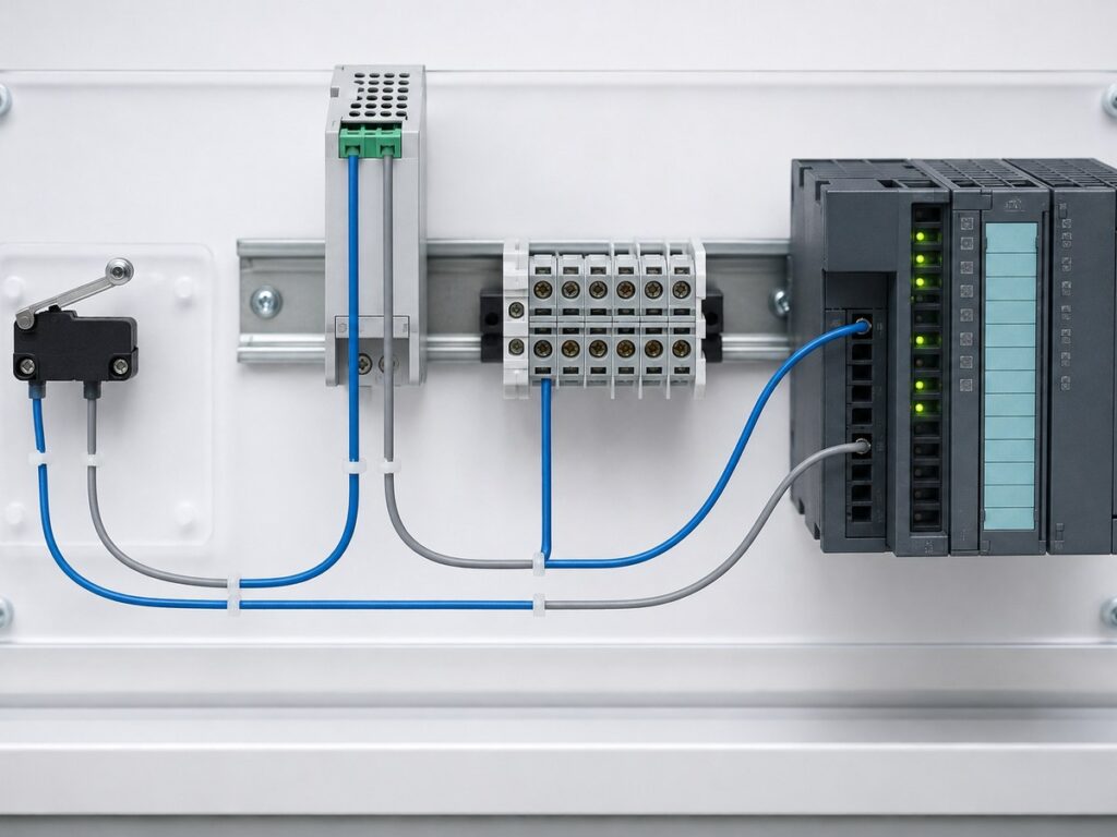
Sinking and Sourcing Input Module Circuits
For a sinking (NPN) DC input module, the PLC terminal internally sinks current from the input point to common ground; wire the micro switch COM terminal to the 24VDC positive power rail and the NO or NC terminal directly to the PLC input channel. For a sourcing (PNP) input module, current flows out of the PLC terminal; connect the switch COM terminal to DC common (0V) and the selected contact terminal to the PLC input. Incorrect polarities will prevent the optical isolators in the PLC input card from turning on.
Filtering Mechanical Contact Bounce
Every mechanical switch produces contact bounce during closing, generating brief voltage oscillations for one to five milliseconds before settling into steady conduction. While electromechanical relays rarely respond to millisecond pulses, high-speed PLC input cards and hardware interrupt routines can misread each bounce as an independent machine cycle. Configure an input filter window of ten to twenty milliseconds within the PLC hardware configuration software to debounce the signal reliably.
Terminal Selection and Mechanical Installation Checks
Electrical wiring integrity depends on appropriate mechanical connections, thermal protection during installation, and proper physical mounting alignment. Poor terminal termination and physical overtravel represent the two primary causes of early micro switch failure in industrial facilities.
Quick-Connect, Screw, and Soldered Terminals
Choose terminal terminations that match your operating environment. Quick-connect push-on terminals (0.187-inch or 0.250-inch) allow fast field replacement on machine assemblies subject to routine maintenance, provided technicians use insulated female crimp receptacles. Screw terminals provide secure, vibration-resistant connections inside heavy industrial enclosures. When soldering leads to solder-lug terminals, limit soldering iron contact to three seconds at 350 degrees Celsius to prevent thermal softening of the internal phenolic casing or distortion of the contact spring mounting.
Preventing Mechanical Overtravel and Heat Damage
Mount the switch body securely using two mounting screws tightened to manufacturer torque specifications, typically 0.4 to 0.6 Newton-meters for M3 hardware. Ensure the operating dog or mechanical cam does not drive the actuator plunger past its specified total travel limit. Excessive stroke transmits impact shocks directly into the internal switch frame, causing housing fractures, spring fatigue, and contact misalignment. Always install external mechanical stops or select roller-lever actuators designed for high-speed angular approach.
Selecting Xurui Micro Switches for Control Enclosures
Industrial equipment requires micro switches engineered to handle diverse electrical loads and environmental conditions. Zhejiang Xurui Electronics Co., Ltd. manufactures precision snap-action micro switches featuring silver alloy contacts, multiple actuator styles, and reliable terminal options suited for control cabinets and field machinery.

| Series | Contact Form | Current Rating | Enclosure Protection | Primary Control Role |
|---|---|---|---|---|
| XZ-15 Series | SPDT (1C) | 15A at 250VAC | IP40 | Heavy-duty general control and limit sensing |
| XV-15 Series (16A) | SPDT, DPDT | 16A at 250VAC | IP40 | High-current pilot circuits and power switching |
| XV-10 Series | SPDT (1C) | 10A at 250VAC | IP67 | Sealed wet, oily, and outdoor washdown areas |
| XWS-6 Series | SPDT (1C) | 6A at 250VAC | IP67 | Subminiature watertight position detection |
| XSS-5 Series | SPDT (1C) | 5A at 250VAC | IP40 | Compact space-constrained electronic panels |
Matching Contact Ratings to Inductive and Resistive Loads
Select contact ratings based on the electrical load type rather than nominal voltage alone. A micro switch rated for 15A under resistive AC heating loads may only carry a 3A rating under inductive DC solenoid or motor clutch duties due to severe contact arcing during circuit interruption. When wiring micro switches into DC inductive circuits, install reverse-biased flyback diodes or RC snubber networks across the inductive load to dissipate stored magnetic energy and extend contact operating life.
Specifying Actuators and Sealing for Machine Quotes
When requesting quotations or technical drawings for OEM equipment builds, specify the exact operating force, actuator style, and required environmental ingress protection. Standard models such as the XV-15 series micro switch with pin plungers or roller levers serve clean control cabinets, while sealed XWS-6 and XV-10 series with factory-potted lead wires provide IP67 protection against cutting fluids and washdown moisture. Provide your operating stroke, duty cycle, and electrical ratings to receive configured samples.
Frequently Asked Questions
How Do You Wire a 2-Pin Micro Switch Versus a 3-Pin SPDT Model?
A 2-pin micro switch contains a single pole single throw (SPST) contact set that is factory-configured as either normally open or normally closed. Wire one conductor from your control power source to the input pin and the second conductor from the output pin to your load or PLC terminal. Unlike a 3-pin SPDT switch, a 2-pin model offers no alternate contact path, meaning you cannot change the resting circuit logic without physically replacing the switch.
Can a Micro Switch Directly Switch an Industrial AC Motor?
Micro switches are primarily designed for pilot-duty control circuits rather than direct fractional-horsepower motor starting. While heavy-duty switches such as the XZ-15 or XV-15 handle high resistive currents up to 16A, direct AC motor starting involves locked-rotor inrush currents six to eight times the running current, causing severe contact welding. As an established industrial control switch manufacturer, Xurui recommends wiring the micro switch contacts in series with a magnetic contactor coil or solid state relay, which then switches the main high-current motor leads safely.
Why Do Safety Circuits Wire Limit Switches in Series Rather Than Parallel?
Safety circuits wire normally closed limit switches in series to establish a fail-safe interlocking loop. If any guard door opens, any limit trips, or any interconnecting wire snaps, current flow ceases immediately and the safety controller drops out. Wiring switches in parallel would create an unsafe bypass condition where a machine continues to run as long as any single parallel switch remains closed, defeating the safety stop function.
XURUI Engineering Team
Industrial SPST toggle switch on a control panel](https://xuruiswitch.com/wp-content/uploads/2026/09/spst-toggle-switch-industrial-control-cover-300x225.webp)
SPST toggle switch product on a clean electronics workbench](https://xuruiswitch.com/wp-content/uploads/2026/09/spst-toggle-switch-cover-300x225.webp)