How to Choose a 3 Position Momentary Toggle Switch for Industrial Control Panels
Choose the return pattern before you choose the pole count. A 3 position momentary toggle switch must send the intended temporary command, return to the required rest position, and match the control circuit behind the panel. A switch that looks similar at the front can hold one command, return from both sides, or move more than one circuit at once.
This guide helps industrial panel builders specify the action, contacts, load boundary, and mechanical interface. It covers selection, not a wiring procedure or a substitute for a safety device.
What Three Positions Mean
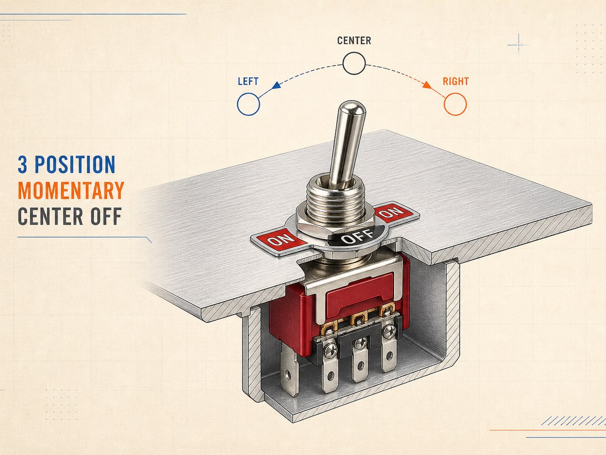
A 3 position momentary toggle switch has a center position and two side positions. In a common center-off layout, the lever rests at center and sends a temporary command only while the operator holds it to one side. This layout suits paired commands such as raise and lower, forward and reverse, or increase and decrease when the control system accepts separate temporary inputs.
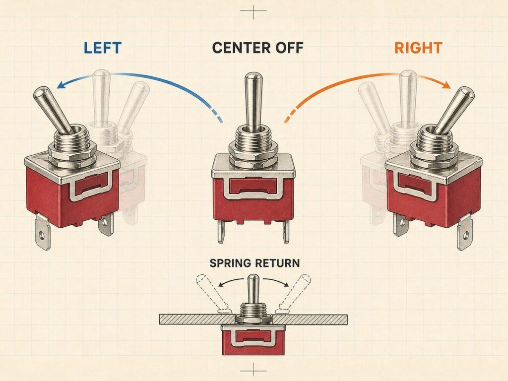
The three positions do not identify the contact arrangement or show whether both side positions return. Read the position marking and the terminal diagram together. The action, rating, and terminal requirements still need to match the exact control circuit.
Select Return Behavior by Operator Task
Return behavior tells the circuit what happens when the operator releases the lever. Match the marking to the required command sequence before comparing current rating, terminal style, or price.
| Position Marking | Lever Behavior After Release | Use It When |
|---|---|---|
| (ON) OFF (ON) | Both side positions return to center OFF. | The panel needs two temporary directional commands. |
| ON OFF (ON) | One side stays selected. The parenthesized side returns to OFF. | The circuit explicitly needs one maintained state and one temporary command. |
Both Side Positions Return to Center
Use an (ON) OFF (ON) arrangement when each direction is a hold-to-run or temporary command and the lever must return to center OFF from either side. One direction can call for an increase, forward, or left command, while the other calls for the paired decrease, reverse, or right command. The controller or interlock must decide how those commands act on the machine.
One Side Returns and One Side Holds
Use a mixed arrangement only when the drawing calls for both maintained and momentary action. In ON OFF (ON), the parenthesized ON position is momentary, while the unparenthesized ON position stays selected. If the circuit only needs temporary commands, a maintained side creates the wrong operator behavior.
Match Contact Form to the Control Circuit
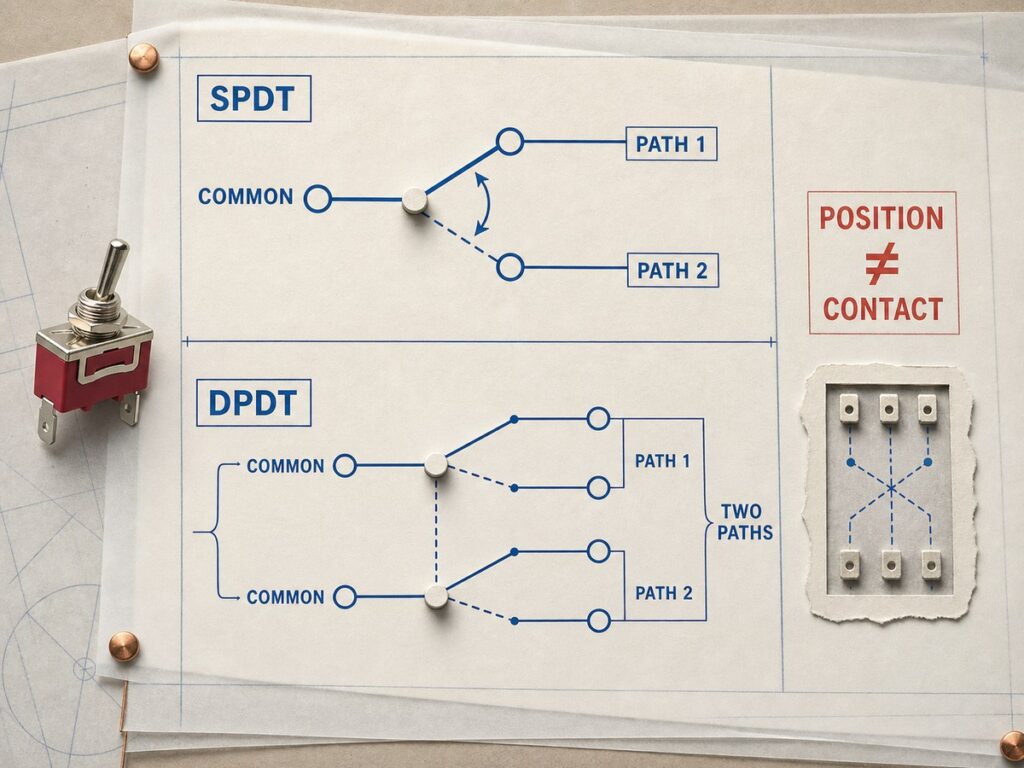
The number of lever positions does not identify the number of conductors that move. Start with the schematic, then confirm the contact form and physical terminal diagram for the exact part number.
One Common and Two Command Paths
An SPDT arrangement can route one common control line to one of two command paths. It often suits a panel input that needs two distinct directions, provided the control drawing specifies that logic. Confirm the center-off and spring-return behavior separately, because suppliers offer the same SPDT contact form with different actions. The terminal drawing must also identify the common and the active path at each lever side.
Two Circuits Moving Together
Choose DPDT only when the schematic requires two changeover paths to move together from one lever. A DPDT switch has two poles and two throws, so you cannot infer its terminal layout from the front legend. A toggle switch symbol identifies the contact logic, while the manufacturer drawing maps those contacts to the actual terminals.
Use Control Logic Before Switch Contacts
A 3 position momentary toggle switch is often an operator input, not the device that switches a motor or other high-demand load. Use the switch to send separate commands to a relay, contactor, drive, PLC input, or other rated control circuit when the load and machine design require it. A spring return ends the operator input at the lever, but it does not by itself define the machine’s stop or safety behavior. For directional movement, the control design must prevent conflicting forward and reverse commands and provide the required machine safeguards.
Confirm the Panel Interface Before Ordering
The correct action and contact form can still fail the build if the electrical duty, terminals, or enclosure interface do not fit. These checks narrow the toggle switch family, but the exact part number still needs to match the panel rather than a generic product photo or family description.
Electrical Duty and Terminal Style
Match the exact AC or DC rating to the circuit voltage, current, load type, and expected inrush. Do not apply an AC rating to a DC load without documentation for that use. Then choose solder, screw, or quick-connect terminals to match the harness, service method, insulation, and rear wiring space.
Mounting, Clearance, and Exposure
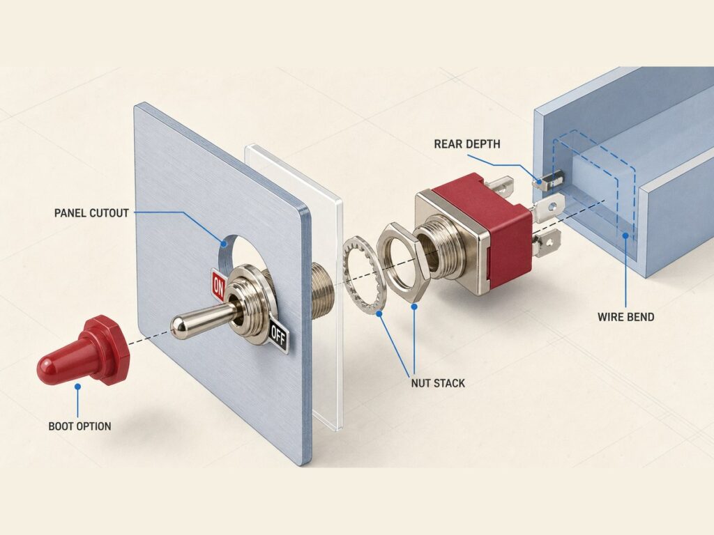
Confirm the panel cutout, bushing length, panel thickness, nut stack, lever travel, rear depth, terminal orientation, and wire bend space. If dust, oil mist, or splash reaches the panel face, specify the exact sealing option and its documented limits. A front boot or cap does not establish protection for the rear terminals, wire exits, or the full enclosure.
Send Exact Requirements With the RFQ
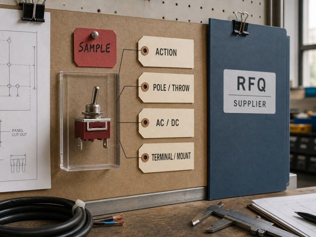
An RFQ should state the required position sequence, which positions are momentary, contact form, control voltage, load type, current, terminal style, panel cutout, rear-clearance limit, and exposure condition. Include the schematic or terminal-function table whenever the control has paired directions or a changeover path.
Before production release, request an exact part-number drawing and sample configuration. Then check lever return, continuity in every position, terminal layout, fit in the finished panel, and the real control response during sample approval.
Frequently Asked Questions
How Do You Test a 3 Position Momentary Toggle Switch Before Panel Installation?
After you isolate the circuit, test the switch against the exact terminal drawing. Confirm the expected continuity at center and at each operated side, then release the lever to confirm the required return action. Finish the sample check by verifying the label, terminal layout, panel fit, and control response in the intended circuit.
Can One 3 Position Momentary Toggle Switch Replace Two Directional Push Buttons?
One 3 position momentary toggle switch can replace two directional push buttons when each lever side sends one separate temporary command and the control circuit accepts that interface. The schematic must show the common and command paths, and the panel design must make the two directions clear to the operator. This choice does not create a safety interlock or prove that the switch can carry the motor load.
What Should a Panel Label Show for a 3 Position Momentary Toggle Switch?
A panel label should identify the command at each lever side and the center rest state. Use functional wording such as Raise / Off / Lower or Forward / Neutral / Reverse when those are the actual control commands. Do not use a generic ON/OFF label when the lever sends two different temporary directions.
XURUI Engineering Team

Industrial SPST toggle switch on a control panel](https://xuruiswitch.com/wp-content/uploads/2026/09/spst-toggle-switch-industrial-control-cover-300x225.webp)
SPST toggle switch product on a clean electronics workbench](https://xuruiswitch.com/wp-content/uploads/2026/09/spst-toggle-switch-cover-300x225.webp)