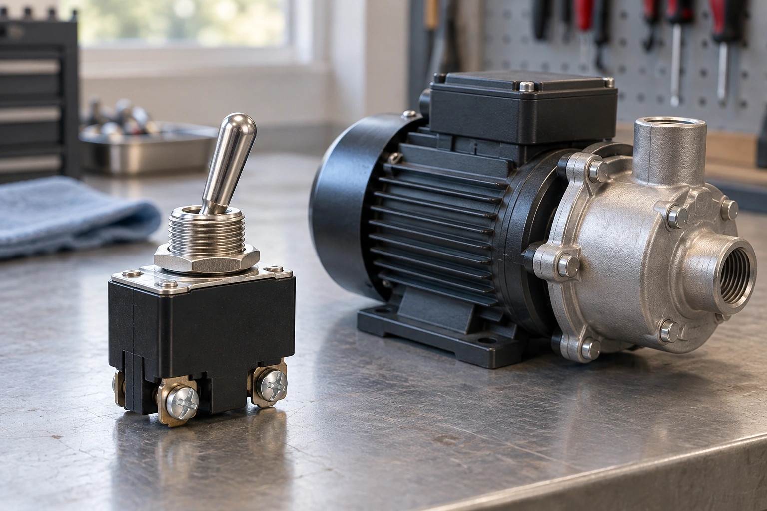
A heavy duty toggle switch’s current rating applies only under specified voltage and load conditions. A 20A marking alone cannot confirm whether it can start a motor or interrupt a DC load. Its ratings must cover both normal operation and the stresses of switching.
Similar-looking switches can have different electrical limits. Comparing those limits with your load requirements helps you decide whether the toggle can switch the load directly or needs to control a separate power device.
Electrical Ratings of Heavy Duty Toggle Switches
Read the current rating together with its voltage, AC/DC designation, load type, and operating conditions. “Heavy duty” alone does not establish a motor rating.
Carrying current describes the thermal limit with contacts closed. Switching capacity covers connecting or interrupting the load. A switch may carry a current it cannot safely interrupt. Electrical life is tested under load; mechanical life is tested without it.
For configurable products such as the XT Series toggle switch, use the complete model code to obtain the ratings for that exact version.

Why a Motor Can Exceed the Switch’s Rated Duty
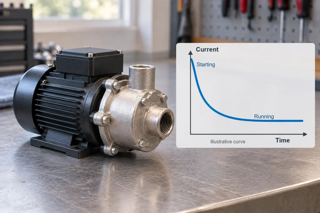
A motor can put more stress on a switch during startup, a stall, or shutdown than its running current suggests. These conditions affect contact heating and the switch’s ability to connect or interrupt the load.
Starting and Stall Currents
Starting current flows as a motor accelerates; stall current flows when it is energized but cannot turn. Use the motor’s actual current and duration data, along with the expected starts per hour, rather than a fixed startup multiplier.
A published motor rating may already cover brief startup peaks above the continuous-current rating. If the switch must disconnect a stalled motor, verify its ability to interrupt that current and coordinate it with overload protection.
Inductive Turn-Off Transients
A motor winding stores energy in its magnetic field. Its inductance opposes a rapid change in current, so opening the contacts can produce a voltage spike as that energy is released. Current may continue through an arc between the separating contacts, causing erosion or welding.
This difference between inductive loads and resistive loads explains why a switch that works with a heater may be unsuitable for a motor with the same running current. Use the manufacturer’s motor-duty data and specified method of suppressing voltage spikes. Adding suppression does not automatically raise the switch’s published rating.
Why an AC Rating Does Not Establish DC Suitability
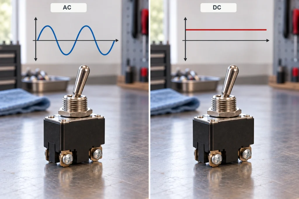
A switch’s ability to interrupt DC cannot be inferred from its AC rating. AC current passes through zero periodically, helping an arc go out. DC has no equivalent periodic current zero, so the contacts face different interrupting conditions. Even at a lower DC voltage, multiplying volts by amps will not give you a valid conversion. A 20A 125VAC marking cannot establish a 24V DC switching rating through a power calculation.
Look for a published DC rating that covers the voltage and load type. Some switches have explicit AC/DC ratings. Others have different limits for each supply type or no published DC rating. Check the load type and supply type separately. An AC motor needs a suitable motor-duty rating, and a resistive DC load still needs an appropriate DC switching rating.
How to Check a Switch Against a Real Load
Compare the load requirements with the published ratings for the exact switch model. Record which requirements are met, which lack supporting data, and which exceed the switch’s limits.
| Load Requirement | Documented Switch Capability | Selection Decision |
| Highest operating voltage and AC/DC supply | Matching voltage and supply-type rating | An AC-only marking does not establish DC suitability |
| Motor, heater, coil, or electronic load | Applicable load rating | A different load category requires further evidence |
| Normal running current | Permitted continuous current under stated conditions | Exceeding the limit rules out that configuration |
| Starting current and duration | Motor rating or permitted inrush conditions | Compare the complete starting duty, not just peak amps |
| Current interrupted during stopping | Applicable breaking capability | Include stalled-load interruption if required |
| Starts and operations per hour | Permitted switching frequency | Excessive operation frequency requires another selection |
| Required service life | Electrical life at a relevant load | Unloaded mechanical life is insufficient |
| Enclosure temperature and wiring | Temperature limits and terminal requirements | Resolve installation mismatches before approval |
Suppose a 24V DC pump draws 8A while running and 40A during startup. These are hypothetical values. The toggle being considered carries only a 20A 125VAC marking.
You cannot approve the switch from those figures. The 8A running current does not establish DC suitability, while the 40A peak alone does not rule the switch out. You still need the startup duration and the switch’s rating for the corresponding DC motor duty.
If the documentation does not cover that duty, choose another switch or let a suitable power device carry the motor load. A continuity test can confirm that the contacts operate, but it cannot establish their endurance under load or their interrupting capability.
When to Use a Relay, Contactor, or Motor Controller
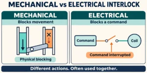
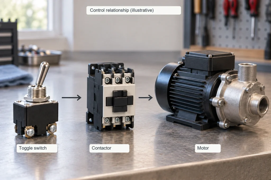
Use a separate power device when the motor load exceeds the toggle’s published limits or the circuit needs control functions the toggle cannot provide. The toggle can switch the motor directly when its ratings cover the full duty. In electrical motor control circuits, the power circuit carries motor current and the control circuit sends commands. Each component must be rated for the circuit it serves.
Relay and Contactor Control
With a relay or contactor, the toggle energizes a coil and separate contacts switch power to the motor. Those contacts need ratings that cover the motor voltage, AC or DC supply, starting duty, and switching frequency. A high resistive-load rating does not establish motor capability.
The toggle must also be able to switch the coil load. Check the coil voltage, the current needed to energize it, and the turn-off transient against the toggle’s ratings. Use the specified coil suppression. A diode across a suitable DC coil can reduce the turn-off surge, though it may delay release. The same arrangement cannot be assumed suitable for AC coils or reversing motors.
Motor Controller Inputs
A motor controller may accept a simple contact closure or require a specified electrical signal. Connect the toggle to that input according to the controller’s instructions, keeping motor power out of the toggle circuit.
Check the input voltage, sensing current, common connection, and command requirements. Low-current inputs need contacts rated for small signals. A high-current switch can be unreliable at such low levels because the signal may not break through films on the contact surface. Check what happens when power returns. A maintained toggle can stay ON during an outage, so the controller must handle that command according to the intended restart behavior.
What to Confirm Before Ordering a Heavy Duty Toggle Switch
Before ordering, make sure the supplier’s documents cover the exact version you plan to install. Ask for:
- The complete part number, including action and terminal suffixes.
- AC/DC and load-specific ratings, including motor duty where applicable.
- Electrical-life data with its test load and operating frequency.
- Terminal instructions, conductor compatibility, and operating-temperature limits.
- Any required approval evidence tied to the ordered configuration.
Obtain any missing electrical data before accepting a sample for the application. Testing under representative conditions can reveal heating or operating problems. A short trial, even if successful, cannot establish the switch’s full service life.
To discuss load compatibility with XURUI, send the supply voltage, load type, running and startup data, switching frequency, and intended model. These details help identify the documents needed to assess the selection.
FAQs
Can I parallel poles to double amp capacity?
No. Connecting poles in parallel does not automatically double a toggle switch’s switching capacity. The poles may not open or close at the same instant, so one can briefly carry or interrupt the full load. Use this arrangement only if the manufacturer provides a rating for that exact parallel configuration.
Why do switch terminals melt under rated load?
A poor connection can add enough resistance to overheat the terminal even when the measured running current is below the switch’s marked rating. Check for loose screws, damaged connectors, poor crimps, or unsuitable conductors. Enclosure heat and startup current missed by the measurement may also contribute. Disconnect power before inspecting the connections, follow the terminal instructions, and replace heat-damaged parts before restoring service.
Can flipping the toggle slowly weld contacts?
Yes, slow movement can contribute to welding if the switch has a slow-break mechanism. When contact movement follows lever speed, moving slowly can prolong arcing. A snap-action mechanism moves the contacts rapidly once it reaches the switching point, largely independently of hand speed. Check the mechanism and its operating limits, and avoid holding the lever near the transition.
External Sources
- OMRON — Precautions for Correct Use of Basic Switches
- Carling Technologies — Switch Learning
- OMRON — Parallel Contacts and Switching Capacity
- OMRON — Wiring Systems Safety Precautions
- OMRON — Contact Protection and Surge Suppressors
- APEM — Switch Terminology and Snap-Action Definition