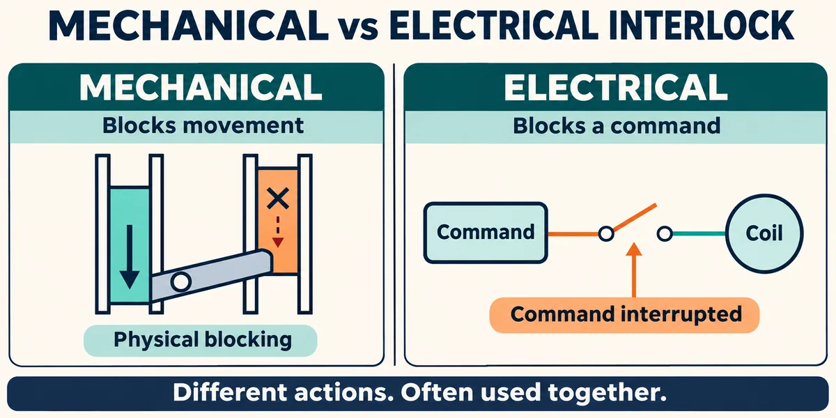
A mechanical interlock uses physical parts to block conflicting actions. An electrical interlock uses contacts or control logic to prevent conflicting commands. Both prevent incompatible functions from operating together, but they act on different parts of the system.
Motor starters, transfer switches, and foot controls show how these methods work and where their limits lie. The focus here is on preventing conflicting operations. Functions that protect people require a separate safety assessment.
Key Differences Between Mechanical and Electrical Interlocks
In a contactor assembly, a mechanical interlock blocks physical movement, while an electrical interlock controls whether a closing command can proceed. The table compares typical arrangements.
| Comparison Factor | Mechanical Interlock | Electrical Interlock |
| Action | Physically blocks incompatible closure | Interrupts or inhibits a conflicting command |
| Typical components | Linkage, pins, cams, or an interlock module | Auxiliary contacts, relays, or controller logic |
| Installation | Requires compatible mechanisms and mounting | Requires suitable contacts, wiring, or programming |
| Control-power loss | Physical restriction remains without control power | Behavior follows the circuit’s power-loss design |
| Flexibility | Usually tied to a defined physical arrangement | Can combine several operating conditions |
| Fault concerns | Wear, damage, binding, or misalignment | Wiring errors, contact faults, or logic faults |
| Inspection focus | Mounting, movement, and blocking action | Contact states, signal paths, and command inhibition |
A mechanical interlock suits a fixed physical restriction between compatible mechanisms. Electrical interlocking can handle decisions based on several signals or operating conditions. Some systems need both. Neither method is universally safer or cheaper. Compare the actions each one blocks and the faults it leaves unaddressed.
How Mechanical and Electrical Interlocks Work
When one function operates, an interlock blocks the conflicting function. A pair of reversing contactors illustrates how mechanical and electrical designs achieve this.
Mechanical Interlocks
A mechanical interlock connects the moving mechanisms of two compatible contactors.
- The first contactor starts to close.
- Its movement shifts the interlock.
- The interlock blocks the second contactor from closing.
- When the first contactor releases, the mechanism returns and clears the second contactor’s closing path.
The parts vary by product. Some designs use pins that engage the contact carriers; others use cams or separate interlock modules. The kit must match the contactor size, mounting orientation, and spacing.
Mechanical blocking does not remove the electrical command from the blocked coil. Electrical interlocking handles that part of the operation, which is why the two methods are often used together.
Electrical Interlocks
A common electrical interlock in motor control circuits places each contactor’s normally closed auxiliary contact in series with the opposite coil. Auxiliary contacts carry control signals, separate from the motor power circuit.
A normally closed, or NC, contact is closed when its operating device is at rest. When the forward contactor operates, its NC auxiliary contact opens the reverse coil’s circuit, cutting off power through that path. The reverse contactor blocks the forward coil in the same way.
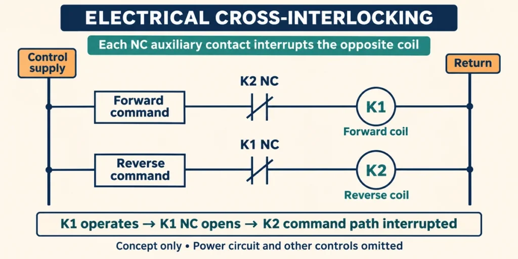
This cross-wiring prevents conflicting electrical operation when the contacts and wiring work as intended. It provides no physical restraint on the contactor mechanism.
Common Applications of Mechanical and Electrical Interlocking
Interlocks can act on power-switching devices or on operator commands. A contactor interlock restricts switching, while an interlock in foot switches prevents competing inputs from being accepted together.
Motor Reversing and Star-Delta Starters
A reversing starter uses two contactors to change the phase sequence supplied to a three-phase motor. Closing the forward and reverse contactors together can create a phase-to-phase short circuit. Electrical cross-interlocking blocks the opposite coil command. A compatible mechanical interlock physically prevents the two contactors from closing together.
In a star-delta starter, the star and delta contactors must remain mutually exclusive. The main contactor, however, normally operates alongside whichever one is selected. The interlocking arrangement must prevent the incompatible connection, and the starter also needs a correctly designed transition sequence.
Open-Transition Automatic Transfer Switches
An open-transition automatic transfer switch disconnects one supply before connecting the other. This sequence is called break-before-make operation. In documented contactor-based designs, electrical interlocking blocks conflicting closing commands, and mechanical interlocking prevents incompatible contact positions. The controller checks the source conditions and initiates the transfer.
Closed-transition equipment allows a controlled, brief overlap between sources. It must be designed for that operation, so the interlocking arrangement described for open-transition equipment cannot simply be carried over.
Foot Switch Systems
A two-direction foot control may use one pedal for upward movement and the other for downward movement. The interlock prevents the control from accepting both commands at once.
A mechanical rocker lifts one side as the other is pressed, keeping the opposite switch from operating. An electrical design evaluates the pedal signals and applies a defined priority or rejection rule. Blocking those inputs does not establish that the downstream power contactors are mechanically interlocked.
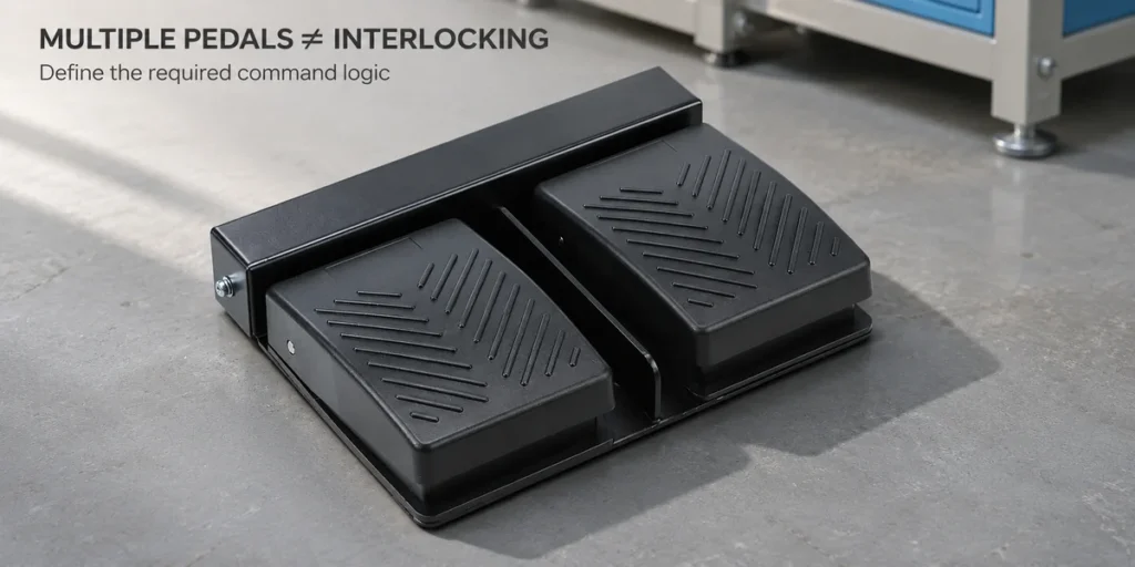
For a multi-pedal control such as the XF Series foot switch, specify the pedal action and contact logic separately from the required interlock behavior. Multiple pedals alone do not provide mutual exclusion.
Do You Need Both Mechanical and Electrical Interlocks?
For a conventional reversing contactor starter, start with a manufacturer-supported arrangement that combines electrical cross-interlocking and mechanical blocking. Electrical interlocking normally removes the conflicting coil command. If that restriction fails, the mechanical interlock blocks incompatible closure. Other equipment faults still need to be addressed.
A foot-switch assembly may achieve the required input exclusion with either a mechanical or an electrical design. The recommendation for reversing contactors does not apply automatically to every operator control. For transfer equipment, retain the interlocking arrangement specified for the complete switch. The transition type and operating mechanism determine which states are permitted. Adding or removing an interlock can change those states.
How to Choose an Interlock for Your Application
Identify the action that must be blocked, then choose a mechanism or circuit that controls it directly.
Select the Interlock Type
- For reversing contactors, select the approved contactor pair, matching mechanical kit, and required NC auxiliary contacts. An incompatible kit cannot provide the intended blocking action.
- For source transfer, select complete transfer equipment with the required transition sequence. An operator command or controller setting alone does not establish physical separation between sources.
- For competing pedal commands, define what should happen if both pedals are pressed: reject both, accept the first, or apply a specified priority. The mechanism or circuit must follow that rule.
Verify Compatibility and Operation
Before approving the arrangement:
- Match the coil voltage and AC/DC type to the control supply.
- Check the auxiliary-contact ratings against the actual control load.
- Confirm the mounting arrangement, spacing, and permitted orientation.
- Define what happens when power is lost and restored.
- Test conflicting command combinations using the manufacturer’s commissioning procedure. If input blocking and physical closure blocking are separate functions, test both.
For help selecting switch components, discuss your control requirements with XURUI. Provide the current model, required contact logic, control load, operating movement, and environment so the component configuration can be reviewed.
Frequently Asked Questions
Can PLC Logic Replace Hardwired Interlocking?
PLC logic can handle routine command interlocking, but it cannot replace a required mechanical interlock. Safety functions need a properly assessed safety control system; ordinary PLC logic alone is insufficient.
Can Mechanical Interlocking Prevent Every Contactor Fault?
No. It blocks incompatible movement but cannot prevent every contactor fault. Detecting welded contacts requires suitable feedback, such as a mirror auxiliary contact, and a monitoring circuit.
Does Interlocking Replace Overload Protection?
No. Interlocking prevents conflicting operation; overload protection responds to excessive motor loading. A motor starter’s overload relay monitors motor current and trips when an overload lasts long enough to threaten overheating. The circuit also needs separate short-circuit protection.
External Sources
- CNC Electric: Interlocking Contactor: Working Principle, Wiring Logic, and Common Applications
- Schneider Electric: Mechanical Interlocks
- Eaton: Contactor-Based Transfer Switch Operation and Maintenance Manual
- Linemaster: Mechanical vs Electrical Interlocks in Foot Switch Systems
- Leuze: Control Functions and Functional Safety
- Schneider Electric: Mirror Contacts in TeSys Contactors