
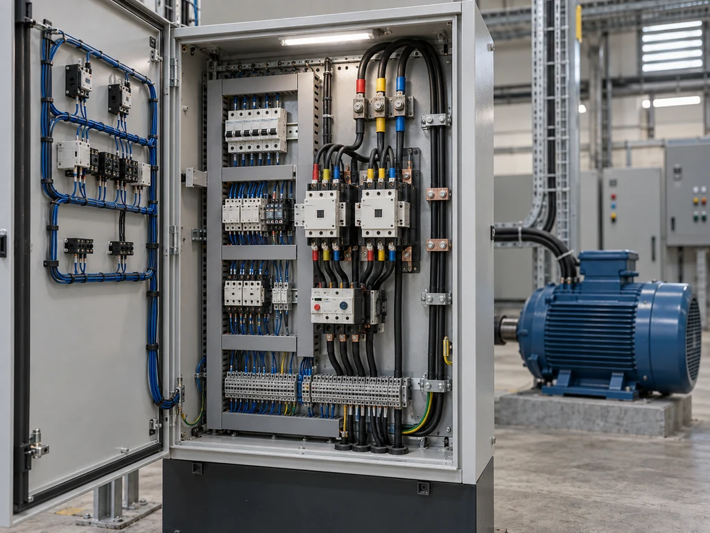
Electrical motor control circuits use command, switching, and protection devices to start, stop, reverse, or automatically operate motors. They separate the high-current power path from the logic that decides when and how the motor runs.
This guide explains the main components, diagram conventions, operating sequence, control methods, and selection checks.
What Is an Electrical Motor Control Circuit?
An electrical motor control circuit sends commands to a contactor, starter, drive, or other switching device. Those commands may come from pushbuttons, selector switches, sensors, relays, or programmable controllers.The power circuit carries motor current. The control circuit operates coils or electronic inputs and may use a different voltage.
Which Components Are Used in a Motor Control Circuit?
A motor control circuit combines switching devices, operator controls, auxiliary contacts, control power, and protection. The required parts depend on the motor, operating sequence, and application risks. Industrial limit switches can also provide position-based commands.
Contactors Versus Motor Starters
A contactor is an electrically operated switch that connects and disconnects a load. Its coil controls the main contacts and associated auxiliary contacts.A conventional motor starter combines a contactor with overload protection. Separate fuses, circuit breakers, or motor protective switching devices may still be needed for short-circuit protection.
Auxiliary Contacts
Auxiliary contacts carry control signals rather than motor current. A normally open contact can maintain coil power after the operator releases Start. Normally closed contacts can provide interlocking or sequence control.Diagrams normally show each contact with its device de-energized.
Control Power Sources
Control power may come from the line, a control transformer, or a DC power supply. The supply must match the coil and pilot-device ratings.A lower control voltage may reduce shock risk, but it does not make the circuit inherently safe. The design must also address fault energy, isolation, grounding, wiring, and local requirements.
Pushbuttons and Selector Switches
Pushbuttons provide momentary commands. A typical station uses a normally open Start contact and a normally closed Stop contact. Selector switches hold positions such as Hand, Off, or Auto.The contact arrangement must match the circuit logic. Similar-looking operators may have different contact blocks and switching actions.
Motor Overload Protection
Overload protection responds to sustained current or another monitored condition that could overheat the motor. When it trips, a normally closed contact usually opens the contactor coil circuit. An overload relay does not normally provide branch-circuit short-circuit protection. Set it according to the motor data, relay instructions, starting conditions, and applicable installation rules.
Short-Circuit Protection
Fuses, circuit breakers, and motor protective switching devices interrupt high fault current. Selection depends on the available fault current, interrupting rating, conductor protection, and tested coordination with the starter. A contactor’s load rating does not show whether it can interrupt a short circuit.
How Do You Read Motor Power and Control Diagrams?
Trace the power and control circuits separately, moving from the supply toward the return path. Device tags connect components shown in different areas or on different sheets.
Power Circuit Layout
The power path usually passes through the disconnect, short-circuit protection, contactor poles, overload elements, and motor. Three-phase conductors are often labeled L1, L2, and L3 on the supply side and T1, T2, and T3 on the load side.
First identify the drawing type. A schematic shows electrical relationships, while a wiring diagram shows terminals and physical connections.
Control Circuit and Ladder Diagram Layout
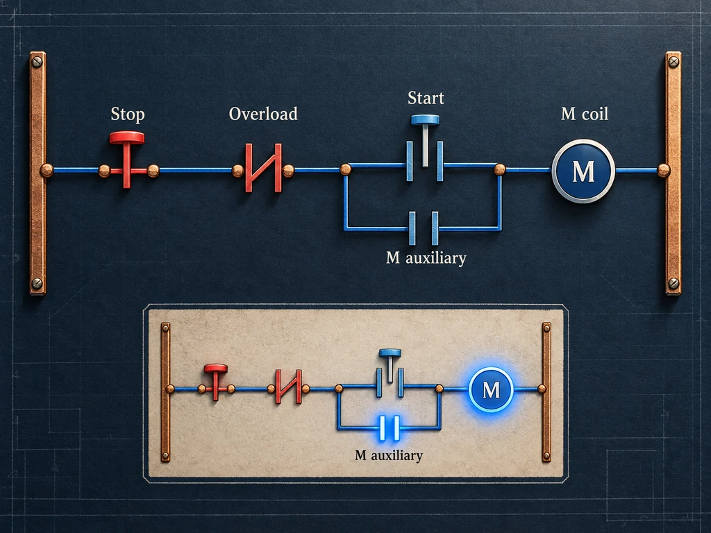
A ladder diagram arranges control functions as rungs between two supply rails. A basic three-wire rung can be shown as:
L1 — Stop (NC) — Overload (NC) — [Start (NO) || M auxiliary (NO)] — M coil — L2
Series contacts create AND logic, while parallel branches create OR logic. The coil energizes only when a complete path exists.
Control Symbols and Device Identification
Symbols show the normal state of contacts, coils, motors, and protective devices. Labels such as M, KM, OL, and CR vary, so follow the drawing legend.
Matching tags identify related devices. For example, a KM1 coil operates contacts marked KM1 elsewhere in the drawing. For field contacts, this COM, NO, and NC wiring guide explains how terminal labels relate to resting and actuated states.
How Does a Basic Start-Stop Motor Control Circuit Work?
A basic start-stop circuit energizes the contactor coil through closed Stop and overload contacts and a momentary Start contact. An auxiliary contact then maintains the command.
Coil Energization from the De-Energized State
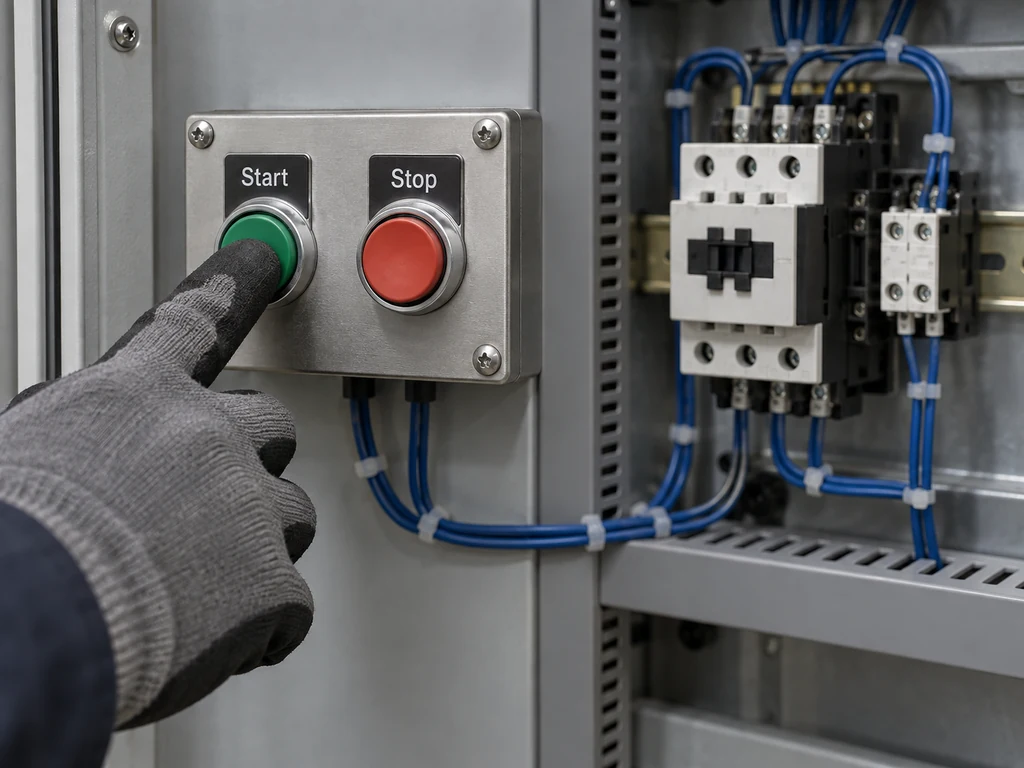
When the coil is de-energized, the main poles and holding contact are open. Pressing Start completes the control path if the Stop contact, overload contact, and other permissives remain closed. The energized coil closes the main poles to power the motor. It also changes the state of its auxiliary contacts.
Holding Circuit Operation
A normally open auxiliary contact is wired in parallel with Start. It closes when the contactor operates, creating another path for coil current after Start is released. The coil remains energized until a series contact opens.
Stop and Overload Trip Responses
Pressing Stop interrupts coil current, so the contactor opens. An overload trip has the same result because its normally closed trip contact opens. Before resetting an overload, check the motor current, mechanical load, phase condition, cooling, and protection settings.
Power Loss and Restart Behavior
A conventional three-wire circuit drops out when control power is lost. Its holding contact opens, so the motor does not restart when power returns. The operator must press Start again. This behavior limits unexpected restarts, but it is not a complete machine-safety function.
How Are Motor Control Circuits Configured for Different Functions?
Control circuits use maintained, momentary, reversing, or automatic commands according to the required operating and restart behavior.
Maintained Two-Wire Control
Two-wire control uses a maintained device, such as a thermostat, float switch, or pressure switch, to energize the starter. If that contact remains closed during an outage, the motor can restart when power returns. Use this arrangement only where automatic restart is intended and allowed by the risk assessment.
Momentary Three-Wire Control
Three-wire control uses momentary Start and Stop contacts with an auxiliary holding contact. A power loss removes coil power and opens the holding path. The motor therefore needs a new Start command after power returns.
Reversing Control and Interlocking
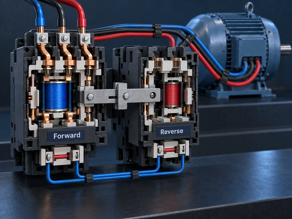
Reversing control changes the phase sequence supplied to a three-phase motor. It uses forward and reverse contactors that must not close together.
Electrical interlocking places each contactor’s normally closed auxiliary contact in series with the opposite coil. Mechanical interlocking physically prevents simultaneous closure. If one spring-return operator sends both directional commands, verify its action with the three-position momentary toggle switch guide.
Sensor-Based Automatic Control
Sensors can replace or supplement manual commands. A position-sensing limit switch may stop travel or start the next operation. Its contact logic, electrical rating, operating travel, mounting, and failure response must fit the circuit. Use a process sensor in a safety function only when the complete system meets the required safety rating.
How Should Motor Control Components Be Selected?
Select components from the motor data, switching duty, control logic, environment, and protection requirements. A matching current value is not enough.
Motor Nameplate and Application Requirements
Record the motor’s voltage, phase, frequency, full-load current, power, speed, and duty. Also define the starting frequency, acceleration demands, reversing or jogging duty, and load inertia. Frequent starting and high-inertia loads can create more heat and contact stress than continuous operation.
Contact Ratings and Utilization Category
Choose contactors and pilot devices for the actual load and switching duty. IEC utilization categories distinguish normal motor switching from more severe operations such as plugging and inching. Confirm the applicable category, operational current, voltage, and switching frequency. Do not use a general resistive-load rating in place of a motor-duty rating.
Control Voltage and Auxiliary Contact Requirements
The coil voltage and frequency must match the control supply. Check the coil burden when it is operated by a PLC output, interposing relay, or small transformer. Count the contacts needed for holding, interlocking, indication, and feedback. Confirm their contact form and control-load rating.
Installation Environment
Temperature, altitude, dust, moisture, vibration, corrosive substances, and enclosure ventilation can affect suitability or require derating. Mounting orientation, wire size, terminal access, and heat dissipation also matter. For mechanical sensors, the limit switch selection guide covers actuator geometry, target movement, travel, enclosure, and mounting.
Protection Coordination
Evaluate the starter, overload relay, short-circuit protective device, conductors, and available fault current as one system. Use manufacturer coordination data for the exact device combination and operating voltage.
IEC 60947-4-1 covers electromechanical contactors and motor starters, but product-standard compliance does not complete the installation design. Confirm the applicable code and project specification.
Need Help Selecting Reliable Control Components?
Please send us the motor data, control voltage, operating duty, contact logic, and installation conditions through Contact XURUI so we can recommend the right components and prepare a quotation.
External Sources
- IEC 60947-4-1:2023—Electromechanical Contactors and Motor-Starters
- Rockwell Automation—Two-Wire and Three-Wire Control
- Rockwell Automation—Basic Two-Wire and Three-Wire Control Diagrams







