An elevator limit switch detects a travel position, but its role determines what happens next. A normal terminal switch supports routine stopping; a final limit protects against excessive travel. Reset behavior and electrical ratings need similar care: releasing a switch may leave the elevator stopped, and a voltage printed on its housing may describe contact capacity rather than coil power.
What Does an Elevator Limit Switch Do?
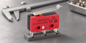
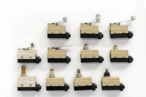
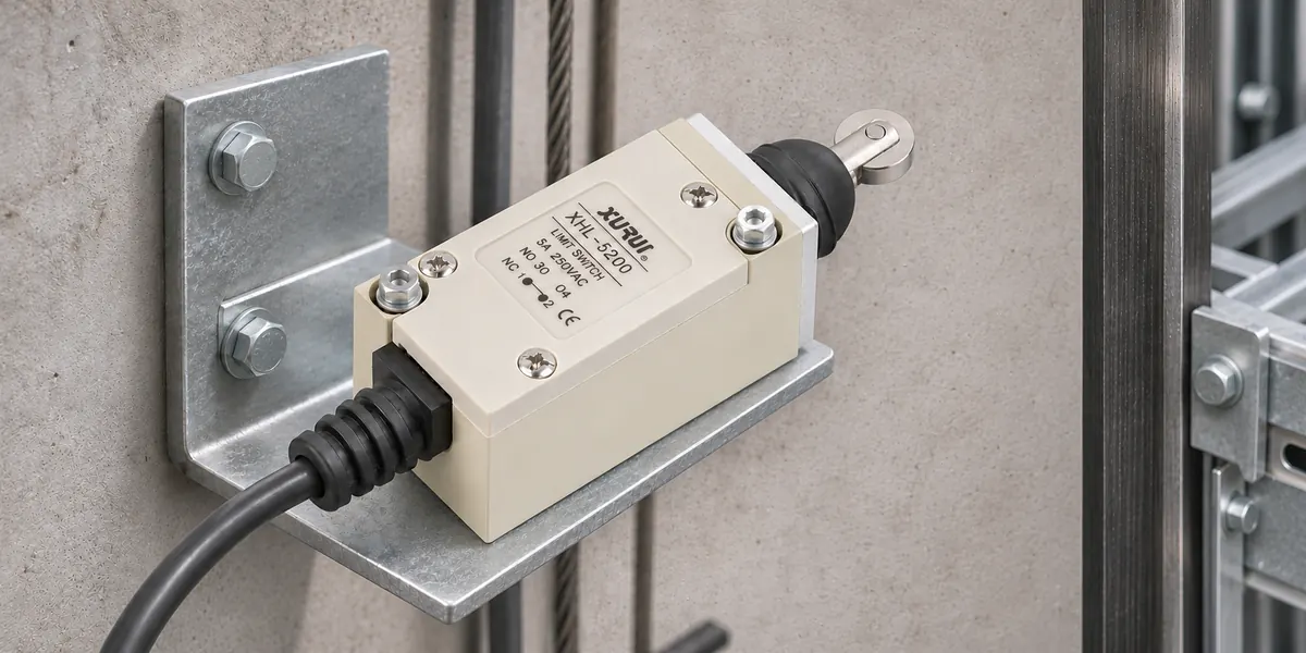
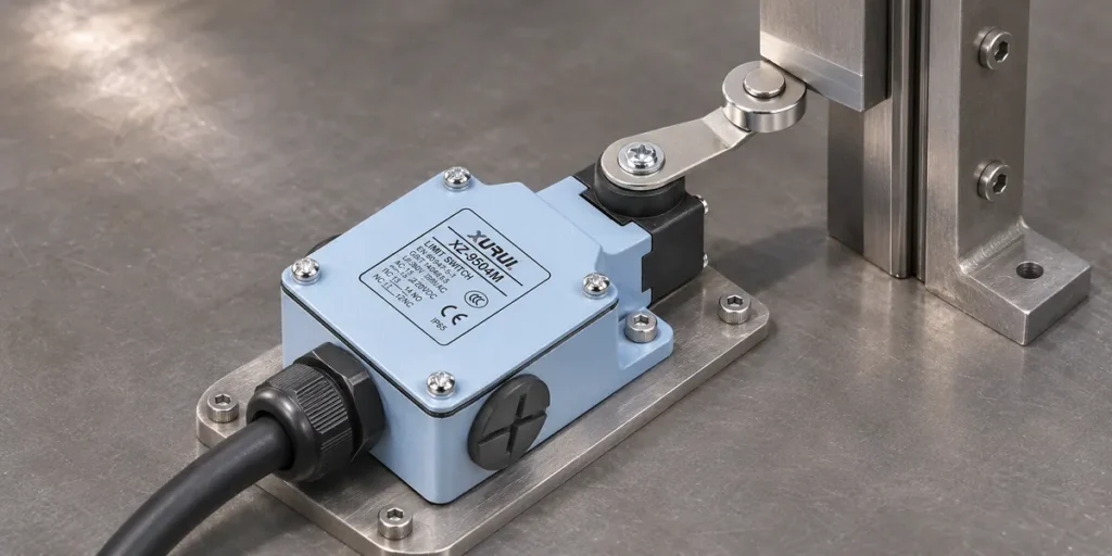
A mechanical switch converts movement into an electrical contact change. A cam or vane presses its roller, lever, or plunger; the resulting signal enters the control or safety circuit. This limit switch operating principle depends on sufficient actuator travel to produce a reliable change.
Normal terminal stopping brings the car to its intended end landing. Final limit protection intervenes beyond that normal stopping position if travel continues. The distinction concerns the circuit’s function, not merely the switch’s appearance. A roller and housing cannot reveal whether a device controls routine movement or performs a safety function.
Can an Elevator Limit Switch Be Reset?
Often, yes. However, restoring the switch’s contacts and restoring normal elevator operation are separate events.
Automatic Return and Latching Reset Mechanisms
A spring-return switch normally returns when the actuating force disappears. A latching mechanism holds its operated state until deliberately reset, either manually or electrically, depending on the model.
Automatic actuation does not imply automatic reset: a moving car can trip a switch that remains latched afterward. A normally closed contact, abbreviated NC, conducts in its specified unactuated state; that says nothing about reset behavior. The mechanism and the controller’s fault memory must be considered separately.
Causes of Continued Shutdown After Reset
The controller may still detect an open safety circuit even after the limit switch returns. Another safety device, damaged wiring, or an incomplete mechanical return can preserve that open condition. A shifted cam can also keep a healthy switch operated. Alternatively, the electrical path may be restored while the controller retains a fault that blocks service.

Limit switch testing distinguishes contact operation from the surrounding circuit. A continuity result obtained with power isolated describes the tested path at that moment; it does not prove that the entire safety system is ready to run.
Conditions for Returning to Normal Service
A qualified elevator maintenance person must establish why the trip occurred and whether the original fault has been corrected. Relevant evidence includes the car’s position, actuator and cam condition, correct contact operation, and the controller’s recorded fault.
Follow the equipment manufacturer’s recovery and functional-test procedure. Confirm that protective functions operate correctly before releasing the lift for service. Clearing a fault record without resolving excessive travel leaves the initiating problem intact. Bypassing the switch removes the protection rather than repairing it.
Does an Elevator Limit Switch Have a Coil Voltage?
A conventional mechanical limit switch needs no coil power. Coils may belong to an electrical reset mechanism or an external relay or contactor.
Contact Ratings on Mechanical Limit Switches
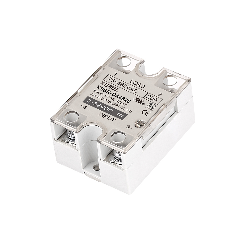
Contact ratings describe the circuit a switch can carry and interrupt under stated conditions. The voltage must be read with the current rating and load category. An electromagnetic coil stores magnetic energy, which produces a voltage surge when its current is interrupted. Its switching stress differs from that of a resistive load.
OMRON’s D4N specifications, for example, separately list thermal current and operating ratings for AC-15 and DC-13 electromagnetic control loads, covering alternating current and direct current respectively. Thermal current concerns heating while carrying current; an operating rating governs switching under its stated load conditions.
Safety switch electrical ratings therefore require more than a comparison of the largest printed number. Rated insulation voltage describes insulation capability; it is not permission to switch any load at that voltage.

Operating Voltage on Electrical Reset Models
Electrical reset models have a separate supply requirement for their reset mechanism. Schmersal’s Z1RM476E-02-024, for example, specifies 24 VDC with a tolerance of −15% to +10%, a maximum switch-on time of two seconds, and a minimum off-duty time of 65 seconds.
These are manufacturer-specific limits. Such a mechanism cannot be treated as a continuously energized coil. Correct voltage alone does not establish correct operation if the permitted pulse duration or recovery interval is ignored.
Relay and Contactor Coil Voltage
In a relay-controlled circuit, the limit switch may interrupt power to a coil. De-energizing that coil releases the associated contacts, producing the intended control response. The coil’s supply rating belongs to that external device.
A contactor’s electromagnetic mechanism needs the specified AC or DC supply to operate reliably. Its coil voltage does not establish the limit switch’s switching capacity. Both devices must suit the circuit, including the coil load imposed on the switch.
| Electrical Parameter | Applicable Component | Verification Source |
| Operating voltage and current | Switch contacts at the stated load category | Exact switch datasheet |
| Rated insulation voltage | Switch insulation system | Insulation specifications |
| Reset voltage and tolerance | Electrical reset mechanism | Model’s electrical data |
| Permitted pulse and recovery time | Electrical reset mechanism | Duty specifications |
| Coil voltage and AC/DC type | External relay or contactor | Coil marking and datasheet |
The table separates three questions: what the contacts can switch, what the reset mechanism needs, and what the external coil needs. A shared voltage value does not make those requirements interchangeable.
What Does EN 81-20 Require for Final Limit Switches?
Applicable Standard Edition and Lift Type
The provisions below refer to EN 81-20:2020 for new passenger and goods-passenger lifts within its scope. Section 5.12.2.1 requires upper and lower final limits for traction, drum, and chain drives, but only an upper final limit for hydraulic lifts.
ISO 8100-1:2026 and ISO 8100-2:2026 have since been published. The project’s governing edition depends on national adoption and its approval basis; publication of a successor does not alone settle a particular installation’s obligations.
Final Limit Positioning and Actuation
Under §5.12.2.1, final limits must act beyond the terminal landings without interfering with normal operation, before the car or counterweight contacts its buffer, or the ram reaches its cushioned stop. Actuation must persist during buffer compression or while the ram remains in that stop zone.
Section 5.12.2.2 requires separate actuating devices for normal terminal stopping and final limits. Its permitted arrangements depend on the drive type.

Safety Circuit Operation and Prevention of Automatic Restart
Section 5.12.2.3.1 permits direct positive mechanical separation of motor and brake supply circuits, or opening an electrical safety device conforming to §5.11.2.
After operation, car and landing calls must remain ineffective, even if hydraulic drift releases the switch. Restoration requires a competent maintenance person (§5.12.2.3.2).
An NC label alone does not establish safety suitability. Direct opening mechanically forces the designated contacts apart, including welded contacts under the specified conditions. The cam must deliver the required direct-opening travel; merely reaching the initial switching point is insufficient.
What Should You Check Before Replacing an Elevator Limit Switch?
Start with the original function and complete part number, including suffixes. A replacement must preserve the required electrical behavior and mechanical actuation, not simply fit the available space.
- Match the contact arrangement, switching sequence, and documented safety function.
- Compare mounting dimensions, actuator direction, operating travel, and permitted overtravel.
- Match contact ratings to the actual voltage, current, and load category.
- For electrical reset types, match supply, tolerance, and duty limits.
- Review environmental ratings, installation instructions, and model-specific approval evidence.
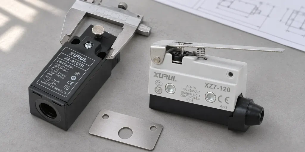
A different lever length or operating point can change where the protective action occurs, even when the mounting holes match. Component documents support selection; they do not establish compliance of the complete elevator installation.
For a component comparison, submit your switch specifications to XURUI with the existing model, circuit function, load, and mounting drawing.
Frequently Asked Questions
Where Is the Elevator Limit Switch Reset Button?
There is no universal location, and some switches have no reset button. A manually reset model may have a local reset actuator; an electrical reset type may receive its command from elsewhere. The exact switch drawing and elevator control diagram identify the relevant device. A controller reset button and a switch reset actuator serve different purposes.
How Often Should Elevator Limit Switches Be Inspected?
The interval follows the elevator’s maintenance program, manufacturer instructions, and local inspection requirements. Rare operation does not eliminate deterioration: contacts can oxidize, seals can age, and mechanisms can lose reliable movement. Routine maintenance checks and statutory functional tests may follow different schedules; a single worldwide interval would conceal that distinction.
How Does a Final Limit Switch Differ From an Overspeed Governor?
A final limit responds to terminal travel position; an overspeed governor responds to excessive speed. In a conventional governor-rope arrangement, the governor can trigger the car’s safety gear to grip the guide rails. A car can exceed a terminal position without reaching the governor’s trip speed, so these protections address different faults.
External Sources
- EN 81-20:2020, German Edition
- Schmersal Z1RM476E-02-024 Technical Data
- OMRON D4N Specifications
- OMRON Limit Switch Safety Precautions
- KONE ISO 8100-1/2:2026 Overview
- Otis High-Rise Elevator Safety Systems