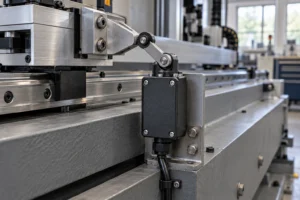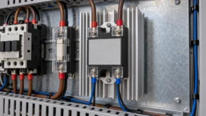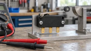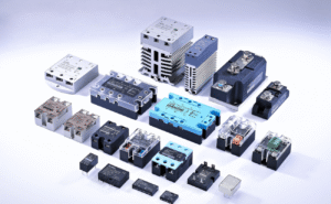
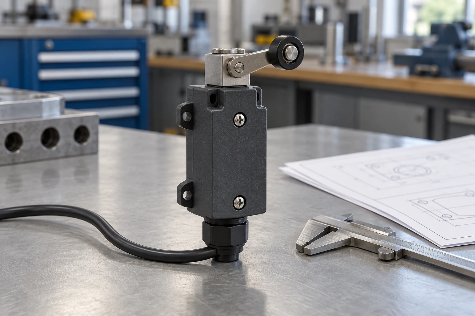
A safety limit switch detects a machine part or guard position and signals the safety control system. Before ordering, confirm that its safety features, electrical ratings, and operating travel match the machine’s requirements.
Mechanically actuated industrial limit switches can look alike while requiring different wiring or movement. Use the exact model’s datasheet and drawings to compare them.
Is the Switch Suitable for Your Safety Application?
Look for documented direct opening contacts that support the machine’s required safety function. Direct opening, also called positive opening, means actuator movement mechanically forces specified normally closed contacts apart. This opening action does not rely on a spring. The documents should identify which contacts provide this function and the movement required to operate them.
The mounting, controller, and stopping devices must also work together. Two safety contacts alone do not establish a Performance Level, which describes the reliability of the complete safety function. For guard doors, consider stopping time. If someone could reach the hazard before it stops, guard locking or additional safeguarding may be required.
Do the Electrical Ratings Match Your Circuit?
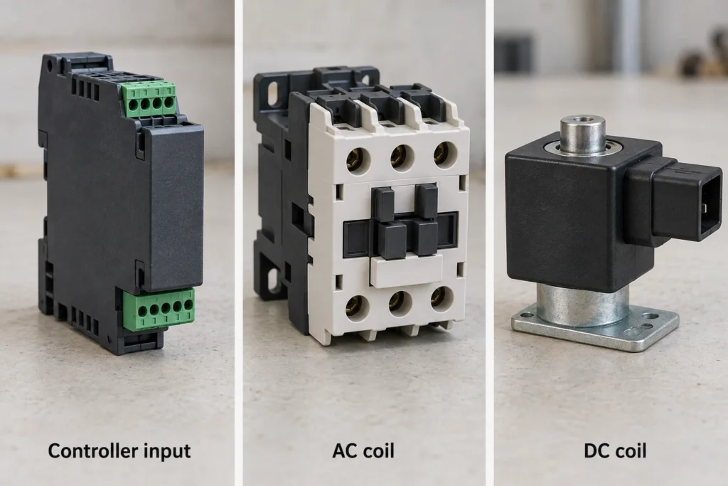
Match the contact arrangement to the controller inputs, then check the switching rating at the circuit’s actual voltage and load.
Contact Arrangement and Timing
A normally closed (NC) contact conducts in its defined unactuated state. A normally open (NO) contact closes when operated. Read the drawing’s reference position carefully; it does not necessarily represent the installed machine’s normal operating position.
The COM, NO, and NC markings identify electrical functions, while the terminal drawing identifies connection points. Match the terminal numbers rather than copying wire positions from another switch. Several contacts may change state at different actuator positions. Their sequence must fit the safety controller’s monitoring requirements, including any permitted difference in timing between inputs.
Load Ratings
Use the switching rating for the actual load. AC-15 and DC-13 cover electromagnetic control loads, such as contactor coils. A resistive-load rating does not establish the same switching capability.
OMRON’s D4N specifications illustrate the difference. They list a conventional thermal current, Ith, of 10 A, but separately rate AC-15 switching at 3 A and 240 VAC, and DC-13 switching at 0.27 A and 250 VDC. Ith concerns carrying current; it does not authorize switching 10 A under every condition.
Low-current controller inputs need attention too. Contacts intended for larger loads may produce unreliable signals at very low current. Compare the input’s voltage and current with the switch’s minimum applicable load. Also verify the specified fuse or other short-circuit protection. Any conditional short-circuit rating applies only with the stated protective device and test conditions.
Will the Switch Fit and Operate Correctly?
Compare the mounting drawing and actuator movement with the machine’s available space and motion path.
Dimensions and Clearance
Check mounting-hole spacing and the actuator’s position relative to the target. Leave room for wiring, opening the cover, and tightening glands or connectors. Use drawing tolerances when checking alignment. The switch must still operate correctly when mounting adjustment or target variation places the parts at their least favorable positions. Secure the mounting against movement that could shift the switching point.

Actuator and Approach Direction
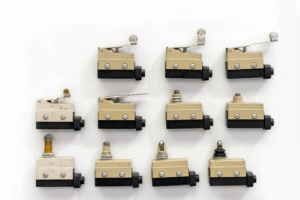
Choose a head the target can engage smoothly in the permitted direction. A plunger needs a suitable pressing path; a roller or lever needs controlled movement without excessive impact or side loading. The XZ-93 series includes these different head options. Specify the selected head with the body, then compare its permitted operating speed and switching frequency with the target’s motion and cycle rate. For a guard arrangement relying on direct opening, guard movement must mechanically drive the required opening action. Simply releasing a spring-loaded actuator does not provide the same action.

Direct Opening Travel and Overtravel
Provide enough movement to reach the direct opening point while remaining within the manufacturer’s permitted travel range. The ordinary operating point is where the contact changes state. The direct opening point is where the specified forced-opening conditions are met. Hearing a click or seeing an input change does not prove that both have been reached.
Overtravel is movement beyond the ordinary operating point toward the total travel position. Read the minimum, maximum, and reference-value notes carefully. A reference-only total travel figure is not an approved operating limit. Check the required opening force or torque as well as travel. Allow for alignment changes and wear, and provide enough return movement for reset. A separate mechanical stop should prevent the machine from driving the actuator too far.

Can the Switch Handle Your Working Environment?
Select a switch whose documented limits cover both normal operation and cleaning. An IP rating describes tested protection against dust and water. It does not prove resistance to every oil, coolant, or cleaning chemical. Temporary immersion protection also does not automatically cover high-pressure washing.
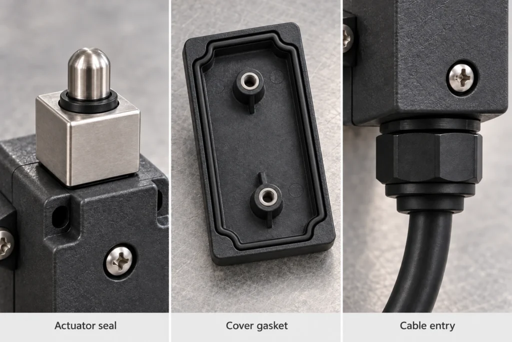
On sealed limit switches, protection relies on the actuator seal, cover gasket, and cable entry. An unsuitable gland or incorrect assembly can compromise the enclosure’s protection. Record the fluid type, cleaning method, and expected temperature, vibration, and shock. Compare these conditions with the product’s published limits and material compatibility information.
Which Model Details and Documents Should You Confirm?
Confirm that the quotation and supporting documents describe the same complete ordering code. Suffixes can change the actuator, contacts, reset arrangement, or connection.
| Document or Detail | What It Should Establish |
| Complete ordering code | Actuator, contact arrangement, reset type, connection, and supplied accessories |
| Current datasheet and drawings | Electrical ratings, dimensions, switching sequence, and operating characteristics |
| Approval documents | The models, contact functions, standards, and conditions covered |
| Safety reliability data | Applicable configuration, load conditions, and assumptions needed by the safety design |
| Installation instructions | Mounting, wiring, sealing, adjustment, and inspection requirements |
If the safety calculation requires B10d, obtain the model-specific value with its test conditions and stated assumptions. This cycle-based data is used to assess dangerous failures. The safety designer also needs the expected operating frequency to apply it. Ordinary mechanical endurance cannot replace B10d, and a cycle rating does not establish a universal replacement interval. Do not substitute another model’s reliability data.
Resolve differences between the quotation, drawings, and supporting records before purchase. A sample can confirm fit and switching behavior, but it cannot establish undocumented safety characteristics. For a model review, send your application specifications to XURUI with the circuit load, actuator layout, operating conditions, and required safety documents.
Frequently Asked Questions
How Often Should a Safety Limit Switch Be Inspected?
Follow the manufacturer’s instructions and the machine’s maintenance schedule. Frequent use or harsh conditions may require shorter intervals. Verify operation after installation, replacement, or relevant maintenance.
What Is the Difference Between a Safety Limit Switch and an Emergency Stop?
A safety limit switch responds automatically to machine or guard movement. An emergency stop is operated by a person. Resetting an emergency stop must not restart the machine.
Can a Safety Limit Switch Replace Lockout/Tagout?
No. It sends a control signal but does not isolate hazardous energy. Maintenance covered by OSHA’s hazardous-energy rule still requires the appropriate energy-control procedure.
External Sources
- OMRON D4N Safety Limit Switch Specifications
- OMRON D4N Safety Limit Switch Datasheet
- Banner SI-LS83 Safety Limit Switch Instruction Manual
- Rockwell Automation Functional Safety Data Sheet
- IDEC Guide to IEC 60204-1 Machinery Electrical Safety
- OSHA 1910.147: Control of Hazardous Energy