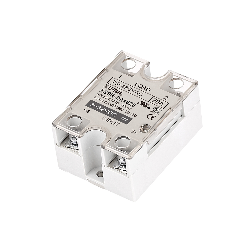
A 40A solid state relay operates reliably only when load current, cabinet temperatures, and branch circuit protection match actual thermal limits. Safe sizing requires checking continuous currents against internal enclosure heat, followed by coupled heat sink and ultra-rapid fuse selection. The stamped 40A label alone never guarantees safe operation.
What the 40A Rating Means
A 40A nameplate rating represents the maximum allowable current under ideal laboratory conditions with an infinite heat sink held at 25°C or 40°C. In actual control enclosures, elevated ambient temperatures reduce usable continuous capacity well below 40A. When selecting solid state relays, treat this stamped value as a theoretical ceiling rather than a guaranteed working limit.
How to Derate a 40A SSR for Continuous Loads
Sizing an SSR for continuous duty requires establishing true electrical peaks and matching them directly against manufacturer thermal derating curves.
Determine Maximum Load Current and Startup Surge
A resistive heater’s nominal current equals rated power divided by nominal voltage. A 4.6 kW heater at 230 V draws 20 A under baseline conditions. Field design requires calculating peak current using maximum positive supply voltage tolerances (such as +10%) combined with minimum element resistance across the working temperature range.
Startup surges demand independent verification. Cold element resistance often drops significantly below hot running resistance, generating high initial current spikes. Compare the initial surge waveform and duration directly against the SSR non-repetitive surge rating curves. Published surge limits define single-event thresholds; recurring surges during routine duty cycles degrade semiconductor junctions over time.
Read the Model-Specific Derating Curve
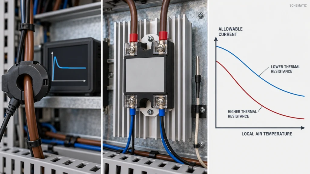
Manufacturer derating curves plot allowable continuous load current against localized ambient air temperature for specific heat sink thermal ratings. Sizing must reference the air temperature immediately surrounding the relay—not general room ambient—while observing datasheet restrictions on vertical fin orientation and module spacing. If the operating point exceeds curve limits, upgrade to a larger heat sink or a higher-rated relay. Note that temperature controller PWM duty cycles do not reduce peak conduction current; thermal sizing must evaluate the longest uninterrupted conduction interval (such as initial cold warmup) rather than an averaged duty cycle.
How to Select the Heat Sink
Dissipating internal semiconductor losses requires establishing an unbroken, low-resistance thermal path from the internal thyristor junction to ambient cabinet air.
Determine Power Dissipation and Thermal Resistance
Solid-state relays generate roughly 1 to 1.2 W of heat per switched ampere due to internal forward voltage drops. Obtain exact power dissipation directly from the manufacturer loss chart at your design current. For a single relay mounted to a dedicated heat sink, calculate maximum allowable thermal resistance using:
- R_θSA ≤ (Tj_design – Ta) / P_loss – R_θJC – R_θCS
In this relationship, R_θSA represents heat-sink-to-ambient resistance, R_θJC is junction-to-case resistance, and R_θCS is thermal interface resistance. Ta denotes maximum local ambient temperature inside the enclosure, while Tj_design represents target junction temperature, maintained 10 to 20°C below absolute maximum limits. For structural mapping of this thermal stack, refer to our heat sink guide.

Lower thermal resistance values yield smaller temperature rises per watt dissipated. If calculated R_θSA is zero or negative, natural convection cannot dissipate the heat; you must lower cabinet ambient temperatures or add forced-air cooling.
Check Mounting and Cabinet Conditions
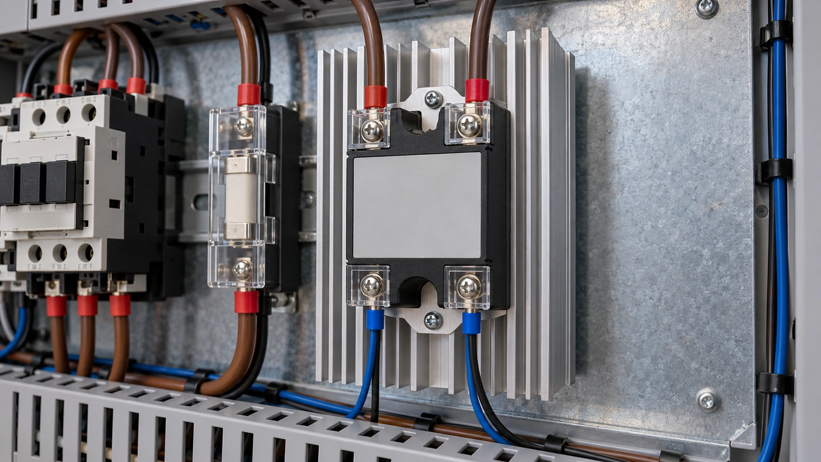
Heat sinks achieve catalog thermal ratings only with unrestricted vertical airflow. Mount fins vertically, maintain convection clearance, and isolate modules from adjacent heat sources. The bare metal baseplate on an SSR only spreads heat; it does not dissipate heat into static air on its own.
Apply thermal interface material (TIM) evenly and torque fasteners to specification (typically 1.5 to 2.0 N·m). Excessive grease, surface voids, or warped plates create high interface resistance that invalidates theoretical calculations. When mounting multiple relays to a shared heat sink, sum all simultaneous thermal losses, and include thermal interlocks to trip power if cooling fans fail.

How to Select the Fuse
Power semiconductors fail within milliseconds during a dead short, making dedicated high-speed semiconductor fuses mandatory instead of standard circuit breakers.
Select the Fuse Type and Current Rating
Standard circuit breakers react too slowly to protect thyristor junctions. Select Class aR or Class gR semiconductor fuses rated to carry continuous load currents and startup transients without thermal fatigue. Size the fuse based on actual operating current and enclosure temperature derating; the 40A nameplate on the relay body must never dictate fuse sizing.
Match fuse voltage ratings and interrupting capacity directly against system supply voltage and prospective short-circuit currents (SCCR). Class aR fuses provide high-speed short-circuit clearing, leaving thermal overload protection to downstream devices as detailed in our SSR protection guide.
Verify I²t and Peak Let-Through Coordination
Total clearing energy (I²t) accounts for both element melting and arc extinguishing. Ensure candidate fuse clearing energy stays safely below the SSR withstand threshold:
- Fuse Clearing I²t < SSR Rated Withstand I²t
Always calculate coordination using total clearing I²t rather than melting I²t. Evaluating only melting values leaves the thyristor unprotected against arc energy during a dead short. Verify peak let-through current (I_peak) against SSR sub-cycle withstand limits. If available fault levels are unverified or component coordination data is unavailable, consulting XURUI engineers with full schematics, load cycles, and upstream breaker curves ensures validated component matching before production sign-off.

Worked Example for a 230V 4.6kW Heater
Applying these thermal and electrical steps to a representative 20A heating circuit illustrates the complete component coordination process.
A 230V, 4.6kW resistive heater draws 20A under continuous conduction, with a nominal resistance of 230² / 4600 = 11.5 Ω. System sign-off requires pairing these baseline figures with enclosure thermal constraints and protection data:
| Parameter | Value | Source or Verification |
| Heater voltage and power | 230V and 4.6kW | Example operating point |
| Nominal load current | 20A | 4600W / 230V |
| Resistance at rated operation | 11.5 Ω | 230V / 20A |
| Maximum operating current | Determine from voltage and resistance limits | Heater specifications and measurements |
| Startup surge | Record current, duration, and repetition | Cold start measurement or heater data |
| Candidate SSR | Exact 40A AC output model | Latest approved datasheet for the exact model |
| Highest local ambient temperature | Measure or establish design maximum | Cabinet assessment |
| Power loss and thermal resistance | Obtain for the candidate model | Manufacturer curves and interface data |
| Heat sink suitability | Confirm against current and temperature | Applicable derating curve and temperature test |
| Fuse coordination | Verify I²t, peak current, and interrupting capacity | Fuse data, SSR limits, and available fault current |
A 40A SSR handles this 20A heater reliably only when manufacturer derating curves confirm continuous 20A capacity at maximum cabinet ambient temperature. Determine exact dissipation at full current, calculate required heat sink thermal resistance, and coordinate high-speed fusing against cold inrush and available fault levels. Sizing without verified thermal and let-through data leaves hardware selection provisional.

Verify Thermal Performance and Fault Shutdown
Empirical testing under worst-case conditions validates thermal calculations and failsafe operation. Run full-load burn-in tests to complete thermal equilibrium at maximum design cabinet ambient temperature during the longest continuous heating phase, logging temperatures at local air, heat sink fins, and the baseplate.

Complete these verification checks before sign-off:
- Confirm components: Match installed part numbers for the SSR, heat sink, thermal interface material, and fuse against approved schematics.
- Verify thermal limits: Confirm measured baseplate and calculated junction temperatures stay within target design thresholds.
- Test independent shutdown: Ensure high-limit safety cutoffs disconnect main line power independently of SSR control signals.
- Document fault protection: Archive coordination records, wire gauge specifications, and terminal torque values.
Solid-state relays typically fail in a shorted state without blowing branch fuses, continuously supplying full power to the load regardless of controller commands. Always install an upstream electromechanical safety contactor driven by an independent high-limit controller to prevent thermal runaway.
Frequently Asked Questions
Can a PLC Transistor Output Drive a 40A SSR Directly?
Yes. Standard 24VDC transistor outputs can drive DC-input SSRs directly if module current capacity meets input requirements (typically 5 to 15 mA). However, check for output card leakage and test pulses; if leakage exceeds the SSR drop-out threshold, install a parallel bleed resistor across the control terminals to ensure clean turn-off.
Why Does a Meter Show Voltage at the Load When the SSR Is Off?
High-impedance multimeters detect benign microamp- to milliamp-level leakage through internal RC snubber circuits and semiconductor junctions in the OFF state. Test with an actual load connected to distinguish normal off-state leakage from a shorted switch. Solid-state relays lack physical air-gap contact isolation; always disconnect upstream power before servicing.
Can Two 40A SSRs Be Connected in Parallel to Increase Current Capacity?
No. Slight variances in forward voltage drop and switching speeds prevent symmetrical current sharing. One relay turns on faster, absorbs excessive load, and fails thermally. Instead, select a single higher-rated SSR or split the heaters into independently switched circuits.
References & Authoritative Sources
- Littelfuse Industrial Solid State Relay Heat Sink Sizing Guide
- Eaton Bussmann Series High Speed Fuse Application Guide
- OMRON Solid State Relay Technical Information