
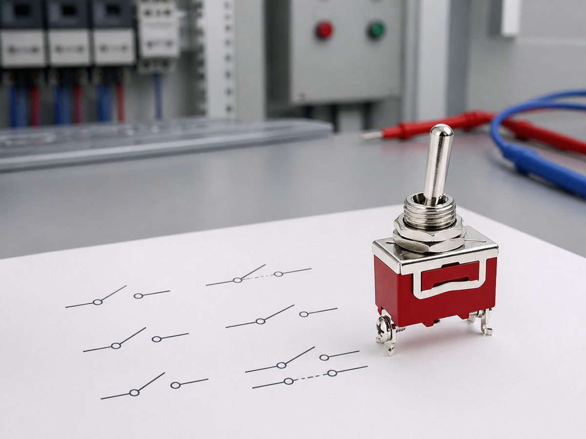
A toggle switch symbol is a contact drawing, not a hardware drawing. It shows the number of poles that move together, the paths each pole can reach, and which terminals carry the circuit. Misread the pole and throw count, and the switch you order will not match the circuit you drew.
This guide covers the four standard toggle configurations, SPST, SPDT, DPST, and DPDT, how to read them on a schematic, and the physical checks that turn a symbol into a correct part number. The symbols follow the same contact logic on IEC 60617 and ANSI-style drawings, so the reading method carries across projects.
What Does a Toggle Switch Symbol Show?
XURUI toggle switch symbol](https://xuruiswitch.com/wp-content/uploads/2026/08/xurui-toggle-switch-symbol-meaning-1024x768-1.jpg)
A toggle switch symbol places a break contact in the circuit line, marks each terminal with a dot, and angles a lever line to the contact. The drawing carries three facts: pole count, throw count, and which terminal is common. Everything else stays out of the symbol.
What the drawing leaves out matters too. Current rating, terminal style, panel cutout, sealing, and whether the lever holds or springs back all come from the datasheet and the part number. Two SPST symbols from different suppliers can represent different physical switches.
| The symbol shows | The symbol does not show |
|---|---|
| Number of poles moving together | Current and voltage rating |
| Paths each pole can reach | Terminal style and size |
| Which terminal is common | Panel cutout and bushing size |
| Contact state in the drawn position | Momentary or maintained action |
How Do SPST, SPDT, DPST, and DPDT Symbols Differ?
XURUI SPST SPDT DPST DPDT symbols](https://xuruiswitch.com/wp-content/uploads/2026/08/xurui-spst-spdt-dpst-dpdt-symbols-1024x768-1.jpg)
Read the label in two steps. The first letters name the poles, S for single and D for double. The last letters name the throws per pole, ST for single throw and DT for double throw. The symbol drawing shows that combination as contacts, terminals, and linkage.
SPST On-Off Control
An SPST symbol is two terminals with a single contact between them. Drawn open, the circuit starts off; closing the contact completes the single line. This layout covers one-circuit on-off jobs such as a lamp, a small solenoid, or a control input.
SPDT Changeover Control
An SPDT symbol adds a third terminal. The common terminal sits in the middle and connects to one of two throws, and the lever drawing shows which path is active in the drawn position. Flipping the lever moves the common to the other throw, which suits source selection or routing one load between two paths.
DPST Two-Pole Isolation
A DPST symbol stacks two SPST contacts and joins them with a dashed line. Both contacts move from one lever, so the switch opens or closes two independent lines together.
- Line and neutral on a rated load, so both conductors break at once.
- Two control or signal lines that must switch together.
DPDT Two-Circuit Changeover
A DPDT symbol stacks two SPDT contacts under one dashed line, giving six terminals: two commons and four throws. One lever routes two circuits between two paths each.
- Paired signal or mode selection in control panels.
- Polarity reversal on small rated DC loads, where crossing the throws swaps the output direction.
| Type | Poles | Throws per pole | Terminals | Symbol behavior |
|---|---|---|---|---|
| SPST | 1 | 1 | 2 | Opens or closes one line |
| SPDT | 1 | 2 | 3 | Routes one common between two paths |
| DPST | 2 | 1 | 4 | Opens or closes two lines together |
| DPDT | 2 | 2 | 6 | Routes two commons between two paths each |
The four layouts serve different circuits, so the choice follows the load. The SPDT vs. DPDT vs. SPST comparison walks through how each layout maps to real switching jobs, from simple on-off lines to paired changeover circuits.
How Should Engineers Read a Toggle Switch Symbol on a Schematic?
XURUI toggle switch continuity test](https://xuruiswitch.com/wp-content/uploads/2026/08/xurui-toggle-switch-continuity-check-1024x768-1.jpg)
Reading a toggle symbol is a three-step check:
- Fix the reference position.
- Identify the common and the throws.
- Trace the linkage lines.
Reference Position and Contact State
Schematic symbols draw the switch in a reference position, the off state unless the drawing declares otherwise. Treat that drawn state as the baseline. A contact shown open in the reference position starts the circuit open, and the lever drawing shows what changes when the switch operates.
Common and Throw Connections
The common terminal is the line that stays connected in every lever position; the throws are the targets it can reach.
- In a boxed symbol, terminal labels such as COM, NO, and NC remove the guesswork.
- In a split drawing, the common line angles toward the throw that is active in the drawn position.
Mechanical Linkage Marks
A dashed line joining two contacts means they move together from one lever. This mark is how DPST and DPDT symbols signal ganged poles, and it matters when the contacts sit in different parts of the sheet. For six terminal layouts, the DPDT switch diagram shows how each terminal pairs up in both lever positions before the first continuity test.
How Should Buyers Match a Symbol to a Physical Toggle Switch?
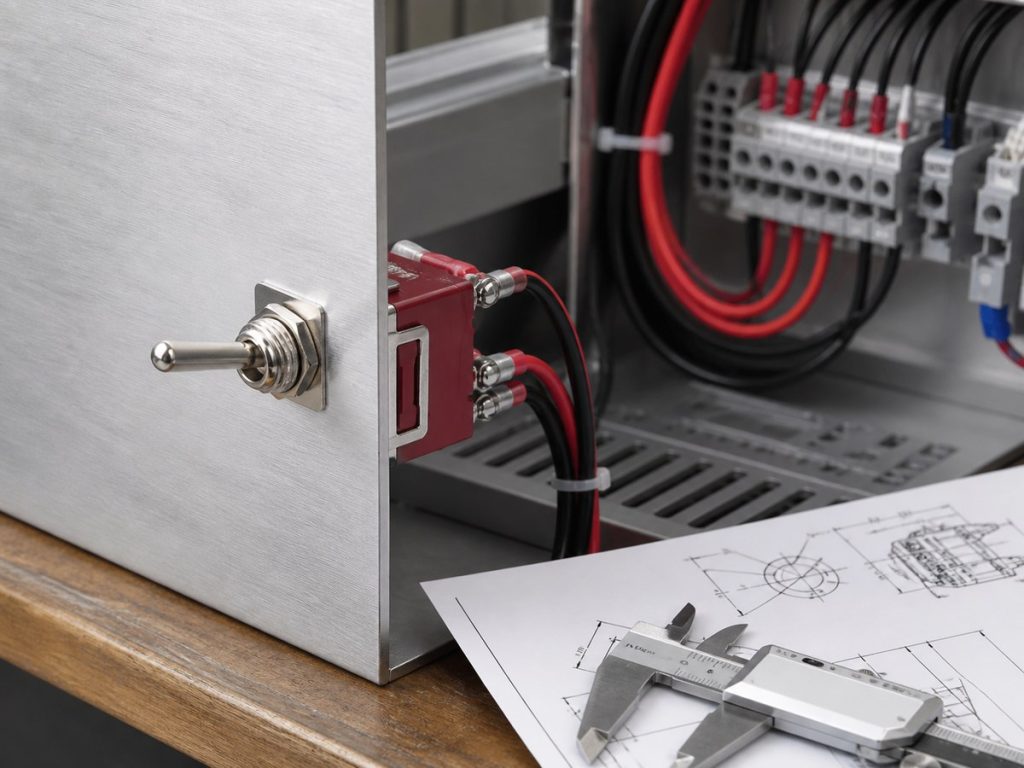
The schematic settles the contact logic. The buyer handles everything the symbol left out: operating action, electrical rating, terminal style, and panel fit. Match all four to the drawing before a part number goes into the BOM.
Operating Action and Position Sequence
The symbol’s throws show the lever positions, not whether the lever holds.
- Maintained switches hold the last position.
- Momentary switches return when released.
The position sequence, ON-OFF, ON-ON, or center-off ON-OFF-ON, has to match the operator task. Hand-reset and auto-reset versions both sit in the toggle switch product range, which covers momentary and maintained action across the same pole and throw options.
Electrical Load and Operating Conditions
A symbol never states the rating, and the rating decides whether the contact survives the load. Match voltage, current, load type, and inrush against the datasheet.
DC arcs do not self-extinguish at a zero crossing the way AC arcs do, so an AC rating does not transfer automatically to a DC load. The XT series from Xurui rates 3A to 15A at 125 to 250VAC by model, and the toggle switch buying guide applies the same rating checks to a full selection, from signal lines to small panel loads.
Terminal Style, Panel Fit, and Manufacturer Documentation
The schematic gives no terminal positions, so the terminal drawing takes over. Solder lugs, screw terminals, and quick-connect blades change how the switch lands in a harness. The XT series toggle switch covers SPST through DPDT with solder (C1), screw (B1), and quick-connect (A1) terminals, so the physical layout can match the assembly method.
Panel fit starts with the bushing: the XT series uses a Φ12 bush and the MTS sub-series uses a Φ6 bush for tighter panels. Before ordering, request the terminal drawing and check it against the schematic. A manufacturer such as XURUI Switch publishes terminal drawings, ratings, and mounting dimensions for every series, which closes the gap between the symbol and the panel.
FAQ
Do SPST, SPDT, DPST, and DPDT Labels Show Whether a Switch Is Momentary or Maintained?
No. The labels describe poles and throws, not the actuator action, so SPST through DPDT tells you the contact layout. Both actions can exist in the same pole and throw layout, so confirm the action from the part number or datasheet rather than the symbol.
Does a Schematic Symbol Show Whether Contacts Are Break-Before-Make or Make-Before-Break?
No. A standard toggle symbol draws contact logic, not switching timing. Break-before-make (the common leaves one throw before touching the other) and make-before-break (the common touches the new throw before leaving the old one) are datasheet properties. Circuits that must never lose continuity need that timing confirmed before ordering.
Can the Same Electrical Symbol Represent a Toggle, Rocker, or Pushbutton Switch?
Yes. The contact part of the symbol describes the electrical path, which is the same across actuator styles. The actuator type shows up as a separate mark on the drawing or in the part number, and it decides the operating feel, panel fit, and mounting. Choose the actuator from the panel design, then verify the contact layout against the symbol.
When Is a Manufacturer Terminal Drawing Needed Instead of a Schematic Symbol?
Whenever the build reaches wiring and panel mounting. The schematic symbol gives contact logic, but the terminal drawing shows physical terminal positions, spacing, bushing size, and mounting dimensions. Compare the two before ordering, because the physical terminal order can differ from the order drawn on the symbol.
Is an I/O Power Mark the Same as an Electrical Toggle Switch Symbol?
No. The I/O mark, a circle and a line, is a power-state label that tells the operator whether the device receives power. A toggle switch symbol is a contact placed in the circuit line, with defined poles, throws, and terminals. The two appear together on equipment fronts, but they answer different questions.
XURUI Engineering Team






