
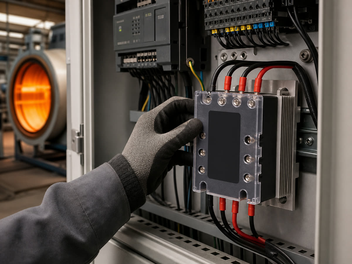
Heating OEMs should source a three-phase solid state relay with a specification that covers the load, control signal, thermal design, protection, and compliance. Heater kilowatts alone cannot show whether a relay will overheat, respond correctly to the controller, or remove power safely after a fault.
Start with the heater circuit, calculate the current in each leg, validate the thermal design, and test the final order code in the production panel.
What Electrical and Control Requirements Should Heating OEMs Define?
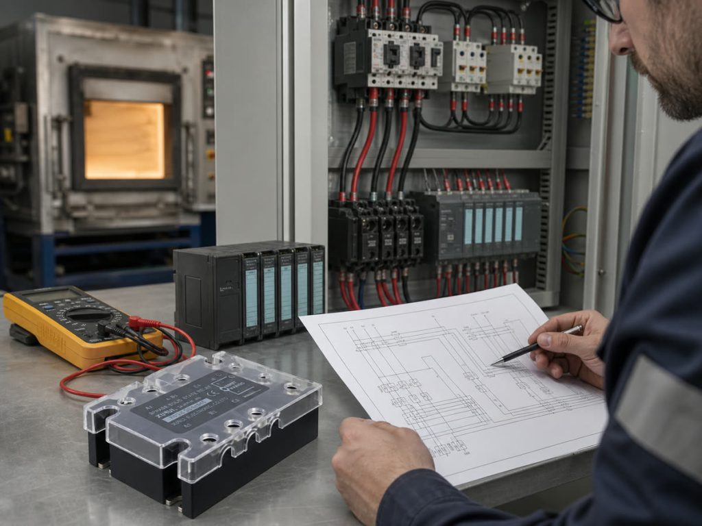
Create one specification row for each heater zone before requesting quotations. Each row should cover the supply, heater connection, controller output, switching method, panel conditions, target markets, and expected production volume.
Line Voltage, Delta or Wye Connection, and Neutral Use
Record the line-to-line voltage, frequency, phase tolerance, and supply variation at the equipment terminals. Then identify whether the heater is delta connected, three-wire wye connected, or four-wire wye connected with a neutral.
A balanced three-wire load does not use the neutral. A four-wire wye heater may use the neutral for unequal phase-to-neutral elements or separately controlled zones. The SSR terminal arrangement must match the approved wiring diagram. Do not select a three-leg relay from total power until engineering confirms the element connection and voltage across each element.
Heater Power, Load Type, and Duty Cycle
Define the load with values that affect current and heat:
- Total rated power and power per zone
- Element material, hot resistance, and lowest expected cold resistance
- Longest continuous on time and normal duty cycle
- Load type, such as direct resistance, transformer primary, or infrared lamp
A resistance heater is usually close to unity power factor after warmup, but transformer-fed heaters, infrared lamps, and mixed loads can draw a different startup current. A high duty cycle also raises the SSR’s average heat loss.
On-Off Switching or Proportional Power Control
Choose the power-control method before choosing the relay. An on-off SSR can support time-proportional control when a PID controller changes the ratio of on time to off time over a fixed cycle. A zero-cross output often fits resistance heating because it begins conduction near an AC voltage zero crossing.
Phase-angle control changes conduction within each AC cycle. That method needs a compatible power controller or solid state voltage regulator, plus checks for harmonics, electromagnetic interference, RMS current, and heat. A random turn-on SSR by itself is not a complete proportional power controller.
Controller Output and Switching Cycle
Match the SSR input to the PLC, temperature controller, or PID output. Check the output voltage range, available current, polarity, off-state leakage, pulse width, and switching period. If one controller output drives multiple SSR inputs, add their input currents before checking whether the controller can turn every channel on and fully release them when off.
Choose zero-cross or random turn-on from the load behavior and control method. Zero-cross switching usually fits time-proportional resistance heating. Choose random turn-on only when the controller must fire away from the voltage zero crossing. Confirm the switching cycle during thermal testing because cycling faster than the heater can respond will not improve temperature control, while a long cycle can widen temperature variation in a low-mass heater.
How Should OEMs Size and Protect a Three-Phase Solid State Relay?
Thermal check of a three-phase SSR](https://xuruiswitch.com/wp-content/uploads/2026/08/heating-oem-ssr-thermal-sizing-protection-1024x768-1.jpg)
Size the relay from the current in each switched leg, then apply the exact series derating curve and coordinated protection. The case rating is not the allowable panel current at every ambient temperature.
Calculating the Line Current for Each Phase
For a balanced three-phase resistance heater, estimate line current with:
I_line = P_total / (sqrt(3) x V_LL x PF)
For a direct resistance heater, power factor is commonly close to 1 during steady operation. Use the equipment value when the circuit includes a transformer or another load that changes power factor.
For a balanced wye heater, each element sees V_LL / sqrt(3). For a balanced delta heater, each element sees the full line-to-line voltage. Confirm current with the approved heater resistance data and wiring diagram, especially when zones are unequal or a neutral carries imbalance current. Use the three-phase solid state relay wiring guide to check terminal and phase arrangements before panel approval.
Accounting for Cold Resistance and Current Margin
Calculate the highest credible current from the lowest element resistance and highest permitted supply voltage. Do not apply one universal inrush multiplier. The cold-to-hot resistance ratio depends on element material, construction, and operating temperature.
Use measured cold resistance or the heater manufacturer’s tolerance data. Then compare the resulting current with the SSR’s repetitive current and surge curve. The XSSR-3 W3, XSSR-3 W4, and XSSR-3H catalog pages recommend keeping resistive load current within 50% to 60% of the relay’s rated load current. Apply the exact thermal curve before approving the order code.
Applying Thermal Derating and Selecting a Heat Sink
Use the highest air temperature at the SSR location, not the room temperature outside the cabinet. Include mounting direction, spacing, airflow, altitude, nearby heat sources, and fouling that may reduce cooling.
Select the heat sink and thermal interface from the exact relay loss and derating data. Check the base flatness, compound or pad, fastener torque, and available ventilation. The answer to whether a solid state relay needs a heat sink depends on installed current and temperature, so do not assume panel metal provides a qualified thermal path.
During sample testing, measure cabinet air, SSR base, heat sink, and terminal temperatures after the system reaches thermal stability. Set acceptance limits below the published component limits and leave an engineering margin for production variation.
Adding Semiconductor Fuses, Surge Protection, and an Independent Cutoff
Assign each protection device one job. Branch protection protects conductors and equipment. A semiconductor fuse limits fault energy through the SSR output only when its voltage rating, interrupting rating, and total clearing I^2t coordinate with the circuit. Surge protection must match the supply and expected transient environment.
Add an independent power-removal device when a closed SSR failure could cause unsafe heating. A separate high-limit sensor and safety controller can operate a rated contactor or disconnecting device. Apply the detailed SSR protection checks to each leg. Do not assume one upstream breaker protects both the semiconductor and the heater process.
How Should Heating OEMs Compare and Qualify SSR Suppliers?
OEM compares three-phase SSR samples](https://xuruiswitch.com/wp-content/uploads/2026/08/heating-oem-ssr-supplier-qualification-1024x768-1.jpg)
Compare suppliers against the same approved specification, then qualify the exact relay, accessories, and production controls. A low unit price has little meaning if the quotation excludes the heat sink, fuse, documentation, or change-control support.
Comparing Quotations, Datasheets, and Order Codes
Send every supplier the same electrical schedule, controller data, cabinet conditions, annual volume, target markets, and required documents. Compare the full order code, not a shortened family name.
Build a comparison table that covers:
| Check | What the OEM should compare |
|---|---|
| Electrical fit | Input range, load-voltage range, current, minimum load, leakage, trigger mode, surge, and frequency |
| Thermal package | Derating curve, power loss, heat sink, interface material, spacing, and mounting direction |
| Protection | Fuse data, surge suppression, terminal cover, and independent cutoff requirements |
| Mechanical fit | Footprint, terminal layout, wire range, torque, DIN rail or screw mounting, and service clearance |
| Commercial terms | Unit price, accessories, minimum order, lead time, forecast flexibility, warranty, and landed cost |
| Documentation | Datasheet revision, drawing, order-code key, declarations, certificates, and change notices |
The XURUI solid state relay range separates three-phase screw-mounted, DIN rail, single-phase, monitoring, protection, and voltage-regulator families. Procurement should keep those functions separate when comparing quotations.
Confirming Certification Scope for Each Target Market
List the required market approvals and equipment certification path in the RFQ. Do not accept a logo on a catalog cover as proof that every model carries the approval. Approval scope varies by series and order code, so ask XURUI for the certificate or listing schedule that covers the proposed model, rating, manufacturing site, conditions of use, and target market.
Testing Samples Under Worst-Case Operating Conditions
Testing a three-phase SSR in a heater panel](https://xuruiswitch.com/wp-content/uploads/2026/08/heating-oem-ssr-worst-case-testing-1024x768-1.jpg)
Test the sample in the production enclosure with the specified heat sinks, interface materials, wiring, terminal torque, fuses, and airflow. Cover the worst approved conditions:
- Highest allowed supply voltage
- Lowest expected heater resistance
- Maximum cabinet temperature
- Densest approved mounting
- Longest continuous duty
Measure line current on every phase, phase imbalance, SSR voltage drop, case and terminal temperatures, control response, off-state leakage, and the independent shutdown response. Repeat cold starts and controller cycling. Approve the sample only when the complete panel stays within its electrical and thermal limits.
Checking Traceability, Change Control, and Supply Capacity
Require lot or date-code traceability, inspection records, and a defined process for reporting nonconforming material. The purchase specification should also require advance notice for changes to the chip, internal assembly, housing, terminal, factory, test method, certification, or datasheet.
Check capacity against forecast, peak demand, minimum order quantity, normal lead time, and recovery lead time. XURUI Switch uses project-based quotations, so the RFQ should state annual demand, batch size, delivery schedule, documentation needs, and the approved order code.
Which XURUI Three-Phase SSR Series Fits the Heating Panel?
Choose the XURUI series from current range, mounting method, and cabinet thermal design. These families are shortlist options, not automatic substitutes. XURUI must confirm the complete order code, heat sink, protection data, and applicable approvals for the production heater panel.
XSSR-3 W3 Horizontal Three-Phase AC Series
The XSSR-3 W3 series is a horizontal, screw-mounted three-phase AC SSR for 24 to 480 VAC loads. The official catalog lists 10 A to 75 A maximum-load-current variants, 3 to 32 VDC or 80 to 250 VAC control options, zero-cross or random triggering, an RC snubber, and an LED status indicator. XSSR-3 W3 fits panels that use a separate, qualified heat sink and need screw mounting in this current range. Confirm the selected current code, trigger type, controller input, mounting surface, and derating curve.
XSSR-3 W4 Three-Phase AC Series
The XSSR-3 W4 series uses a horizontal, screw-mounted package for higher current. The official catalog lists a 24 to 480 VAC load range and 75 A to 200 A maximum-load-current variants, with DC or AC control options, zero-cross or random triggering, an RC snubber, and an LED indicator. Use the XSSR-3 W4 curve for the selected current code because a higher nameplate rating does not remove thermal limits. Verify heat concentration, terminal temperature, fuse coordination, conductor size, and service clearance in the production enclosure.
XSSR-3H DIN Rail Mounted Integrated Series
The XSSR-3H DIN rail mounted three-phase integrated AC SSR combines a three-phase relay assembly with an integrated heat sink and DIN rail mounting format. The catalog lists a 24 to 480 VAC load range, 10 A to 60 A maximum-load-current variants, DC or AC control inputs, and zero-cross or random triggering. Size the XSSR-3H from its load-current versus ambient-temperature curve. The integrated heat sink simplifies installation, but it does not remove current derating, airflow, spacing, or cabinet-temperature limits.
Frequently Asked Questions
Can Three Single-Phase SSRs Replace One Three-Phase SSR?
Yes, three single-phase SSRs can control a three-phase heater when engineering validates simultaneous control, ratings, heat sinks, fuses, wiring, failure detection, and the safety shutdown. The arrangement may improve leg-level service but uses more panel space and parts. Do not mix unmatched models or assume they will share temperature equally.
Can a Three-Phase Heater Be Controlled by Switching Only Two Legs?
Two-leg switching can control some ungrounded three-wire delta or wye heaters because opening two phases interrupts the load current. Use three-leg control for grounded wye heaters, inside-delta arrangements, and three-phase phase-angle control. The unswitched conductor remains connected to the supply, so two-leg control does not provide isolation.
Why Is Voltage Present at the Heater When the SSR Is Off?
An AC SSR can pass a small off-state leakage current through its semiconductor output and snubber circuit. A high-impedance meter may display voltage even when the available current is too low to heat the element normally. Treat the circuit as energized until a qualified person isolates it and verifies the absence of hazardous voltage.
How Can an OEM Detect a Failed SSR Leg or an Open Heater Element?
Measure current in each phase and compare the readings with the commanded state and expected heater load. Phase-current sensors, a current-monitoring relay, or controller logic can flag a missing phase, an open element, or current that continues after the off command. Temperature deviation can support the alarm, but it reacts more slowly and should not be the only fault signal.
Can AC SSR Outputs Be Connected in Parallel to Increase Current Capacity?
Do not parallel standard AC SSR outputs unless the manufacturer provides an approved current-sharing design for the exact models. Small differences in voltage drop and temperature can make one SSR carry more current, heat faster, and take still more load. Select one correctly rated output or use a manufacturer-approved higher-current assembly instead.
XURUI Engineering Team






