
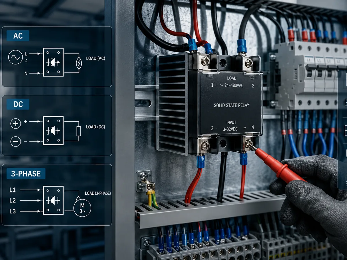
A solid state relay wiring error usually starts with one mismatch: the input side, output side, load type, polarity, or thermal design does not match the relay. Do not wire an AC SSR like a DC SSR, and do not copy a single-phase diagram for a three-phase load.
This guide explains how to check SSR terminals, wire AC, DC, and three-phase loads, protect the circuit, and choose an SSR series for common B2B control panel and automation setups.
What should you know before wiring a solid state relay?
Before wiring a solid state relay, confirm the control input, load output, voltage type, current rating, load position, and polarity. An SSR is not a mechanical relay with different packaging. The output device, leakage current, heat path, and load type all affect whether the wiring is safe and reliable.
Input and output terminals
Most SSRs separate the control side from the load side. The input terminals receive a control signal from a PLC, temperature controller, sensor output, or manual control circuit. The output terminals sit in series with the load and the power source.
Check the printed terminal diagram before connecting wires. Panel SSR terminal numbers often place 3 and 4 on the input side, and 1 and 2 on the output side, but the exact layout changes by series. A DC input also has polarity, so reversing the input can keep the relay from turning on.
Load type, voltage, and current
Match the SSR output to the load before checking the wiring path. Use AC output SSRs for AC loads. Use DC output SSRs for DC loads. A resistive heater, motor, solenoid, transformer, and LED driver can draw different surge current even when the nameplate current looks similar.
Use the load current after derating, not only the steady running current. SSRs generate heat when conducting current, so a relay selected too close to the load rating may overheat inside a closed cabinet.
| Checkpoint | What to verify | Why it matters |
|---|---|---|
| Control input | AC or DC input voltage, input current, and polarity | The controller must supply enough signal current without overloading its output. |
| Load output | AC or DC output type | An AC SSR may not turn off a DC load, and a DC SSR will not behave like an AC zero-cross device. |
| Load current | Running current, inrush current, and duty cycle | Heat and surge current affect relay size, fuse choice, and heat sink selection. |
| Load behavior | Resistive, inductive, capacitive, or electronic | Motors, solenoids, transformers, and LED drivers need more protection margin. |
| Environment | Cabinet temperature, airflow, and mount surface | SSR current capacity drops as temperature rises. |
Power source, load position, and polarity
Wire the SSR output in series with the load, so the SSR controls current flow to the load. In an AC panel, the SSR often switches the line conductor and the load returns to neutral or the other phase conductor. In DC circuits, the SSR must match the intended high side or low side switching path and the output polarity.
Do not use the SSR as a service disconnect. An SSR can leak a small off-state current, and a failed output can remain closed. Use a breaker, disconnect switch, contactor, or safety-rated device when the equipment needs visible isolation or a safety stop.
How to wire SSRs for AC, DC, and three-phase loads
Wire an SSR by putting the output terminals in series with the load and connecting the input terminals to the control source. The circuit changes by load type. Single-phase AC wiring uses a line-load path, DC wiring adds polarity, and three-phase wiring switches multiple phase legs.
| Wiring setup | Typical output path | Main check | Common mistake |
|---|---|---|---|
| Single-phase AC load | Line to SSR output, SSR output to load, load to neutral or return line | AC output rating, load current, and heat sink | Using a DC SSR or undersized heat sink |
| DC load | DC supply to SSR output, SSR output to load, load back to supply | Output polarity and DC voltage rating | Using an AC SSR on DC |
| Three-phase load | SSR switches the required phase legs in a three-phase circuit | Three-phase SSR type, phase voltage, current, and heat | Copying a single-phase diagram |
| AC voltage regulation | Regulator controls conduction angle for AC power control | Regulator type, load type, and control method | Treating a voltage regulator as an on/off SSR |
Single-phase AC SSR wiring
For a single-phase AC load, place the SSR output in series with the load. A typical path is line power into one SSR output terminal, the other SSR output terminal to the load, and the load back to neutral or the other line conductor. The input terminals connect to the controller output.
Zero-cross AC SSRs turn on near the AC waveform crossing point, which helps reduce switching noise for heater and other steady resistive loads. Random turn-on SSRs can turn on at any point in the waveform, which fits phase control or fast timing needs. Choose the type from the load and control method, not from habit.
DC SSR wiring and polarity
DC SSR wiring depends on polarity. The output side normally has a marked positive and negative path, and the input side may also be polarity sensitive. Confirm both before applying power.
A DC load may not turn off through an AC SSR because an AC SSR output often depends on AC current crossing zero to stop conduction. For a deeper explanation, see AC SSR on DC load. In a new design, select a DC output SSR when the load is DC.
Three-phase SSR wiring
Three-phase SSR wiring uses a relay or contactor package built for three-phase loads. The output side switches the required phase legs, and the input side still uses a control signal from the controller. Check whether the design switches two legs or three legs, because the wiring diagram and protection layout will differ.
Use a three-phase SSR when the load is a three-phase heater, motor-related control circuit, or other balanced industrial load that needs solid state switching. Confirm the phase-to-phase voltage, current, load type, and heat sink area before sizing the device.
Zero-cross, random turn-on, and AC/DC mismatch
Zero-cross and random turn-on describe how an AC SSR starts conduction. Zero-cross switching suits heater and steady resistive loads because the SSR turns on near the AC zero point. Random turn-on suits circuits that need immediate triggering or phase angle control.
Do not mix this choice with AC versus DC output selection. A zero-cross AC SSR is still an AC output device. A DC load needs a DC output SSR unless the datasheet specifically states another approved wiring method.
How to protect and test an SSR wiring setup
Protect an SSR wiring setup with the right fuse or breaker, surge suppression, heat sink, wire size, and first-power test. SSR protection is not only about short circuits. It also controls heat, voltage spikes, inrush current, off-state leakage, and wiring errors before the system enters service.
Fuse, breaker, and surge protection
Use short circuit protection sized for the load, wire, and SSR rating. The design may need a fast-acting semiconductor fuse when it must protect the SSR output device from a fault. A standard breaker may protect the branch circuit but may not react fast enough to save the SSR.
Inductive loads can produce voltage spikes when current changes. Use the suppression method recommended for the load type, such as a varistor, RC snubber, or flyback path in a DC circuit. Place protection close to the source of the surge when the wiring layout allows it.
Heat sink and derating
An SSR drops voltage across its output device while current flows, and that power becomes heat. The relay base must transfer heat into a heat sink, panel, or thermal mounting surface. Cabinet temperature, airflow, load current, duty cycle, and mounting compound all affect the final operating temperature.
Do not size the relay by current alone. The heat sink and derating curve decide whether that current is practical inside the cabinet. For more thermal selection detail, see Do solid state relays need a heatsink?.
Pre-power checklist and initial test
Before applying load power, test the wiring in stages. Keep the load disconnected when checking the control signal if the system design allows it. Then apply power with a safe test load or controlled condition before the SSR runs the real machine load.
Use this checklist before first power:
- Confirm the SSR input voltage matches the controller output.
- Confirm the SSR output type matches AC or DC load power.
- Check DC polarity on input and output terminals.
- Verify the load current, inrush current, fuse, and wire size.
- Confirm the heat sink, mounting torque, and airflow.
- Check that a separate disconnect or safety device handles isolation.
- Measure the output state with the controller off and on.
- Run the load briefly, then check case or heat sink temperature.
How to choose an SSR series for different wiring setups
Choose an SSR series from the wiring setup, load type, mounting space, current range, and protection need. Xurui lists single-phase, three-phase, DIN rail, compact inline, monitoring, and current-protection SSR options, so the right match depends on the cabinet layout and load behavior.
Xurui Switch manufactures B2B industrial control switches and SSR products for automation, manufacturing, and control systems. The solid state relay supplier category includes on/off SSRs, AC voltage regulators, three-phase models, DIN rail models, and compact inline models.
| Wiring need | Xurui SSR series to review | Fit for the setup |
|---|---|---|
| Standard single-phase AC control | XSSR-W6 Solid State Relay Series, XSSR-W1, XSSR-W2, XSSR-W5, XSSR-W9, XSSR-W12, XSSR-W15 | Control cabinets, heating control, lighting control, and general automation loads |
| Higher-power single-phase AC loads | XSSR-M1 to M6 High-Power AC Solid State Relay | Industrial heaters and higher current AC switching where engineers plan thermal design from the start |
| Three-phase load control | XSSR-3H Series DIN Rail Mounted Three-Phase Integrated AC Solid State Relay, XSSR-3 W3, XSSR-3 W4 | Three-phase heating and industrial load circuits that need an integrated SSR package |
| DIN rail cabinet wiring | XSSR-H Series, XSSR-3H Series | Panels where rail mounting, compact layout, and service access matter |
| Compact or inline wiring | XSSR-P1 to P3, XSSR-P4 to P6 | Tight equipment layouts and small control modules |
| Monitoring wiring | XSSR-JK W2 Series Monitoring-Type Single-Phase AC Solid State Relay | Circuits where the panel needs SSR state feedback |
| Current-protection wiring | XSSR-F W2 Series Horizontal Single-Phase AC Solid State Relay with Current Protection | Single-phase AC circuits that need integrated current protection features |
| AC power regulation | XSSVR-W1/W2, XSSVR-VA W2, XSSVR-CA W2, XSSVR-3P | Heating or power control where the design needs phase angle regulation instead of simple on/off switching |
Single-phase and three-phase wiring
Use a single-phase SSR for single-phase heaters, lamps, and control loads. Use a three-phase SSR series for three-phase loads, especially when the panel needs a cleaner package than separate single-phase relays. Xurui’s SSR catalog includes current bands such as 10A, 25A, 40A, 80A, and 100A by series, so final selection should follow the datasheet and derating curve.
DIN rail, compact, and inline wiring
DIN rail SSRs fit control cabinets where the installer needs organized wiring and service access. Compact inline SSRs fit small equipment where board space, enclosure depth, or wire routing is tight. Do not choose the smallest package by footprint alone, since thermal path and load current still set the safe operating range.
Monitoring and current-protection wiring
Monitoring and current-protection SSRs fit panels that need more than basic on/off switching. A monitoring type can support feedback wiring, while a current-protection type can help the circuit respond to abnormal current conditions. These features do not replace external fuses, breakers, disconnects, or safety controls.
FAQ
Why does a solid state relay still show voltage when it is off?
A solid state relay can show voltage when off because SSR outputs can have small leakage current and may include internal snubber components. A high impedance meter can detect this ghost voltage even when the load cannot run. Test with the proper meter method and check the datasheet leakage value before assuming the SSR has failed.
Why will a small LED or indicator lamp not turn off with an SSR?
A small LED or indicator lamp may stay dimly lit because SSR off-state leakage current is enough to feed a small current load. This happens more often with neon indicators, LED lamps, and electronic drivers. Add a proper bleed resistor or choose a relay type recommended for small loads.
Can a PLC output drive a solid state relay input directly?
A PLC output can often drive an SSR input directly when the PLC output voltage, output current, and output type match the SSR input. Check sourcing or sinking logic, DC polarity, and common reference wiring. If the PLC output is marginal, use an interposing relay or driver module.
Can a solid state relay be used as the only safety disconnect?
Do not use a solid state relay as the only safety disconnect. SSRs can leak current when off and can fail in a closed state. Use a rated disconnect, breaker, contactor, safety relay, or safety interlock circuit where the equipment needs lockout, service isolation, or emergency stop behavior.
What does it mean if an SSR fails closed?
An SSR fails closed when the output continues conducting even after the control input turns off. The load may stay energized, which is why critical systems need upstream protection and a separate isolation device. Replace the SSR, inspect the load for surge or overcurrent causes, and verify the heat sink before restarting.
XURUI Engineering Team






