
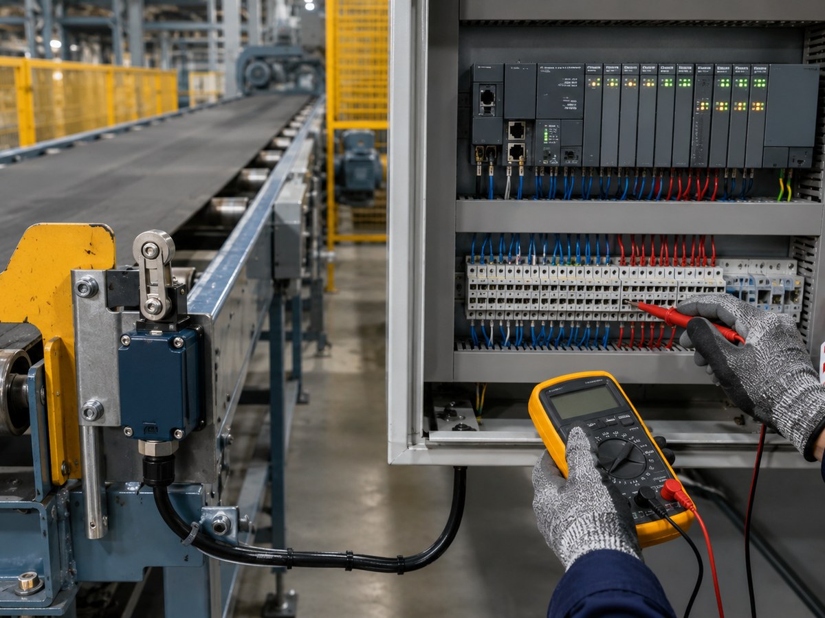
On a conveyor, a limit switch wired for an end-of-travel stop or guard interlock is the last circuit element between a jammed load and a damaged drive, or between an open guard and a moving belt. Getting the wiring right means choosing the correct contact type for the failure mode, matching the contact rating to the actual circuit load, and mapping the switch output to PLC input logic.
This guide covers NO versus NC contact selection, contact rating parameters for conveyor duty, PLC input wiring polarity, a numbered test sequence under lockout/tagout, and a commissioning checklist for controls technicians, panel builders, and project engineers.
Choosing NO or NC Contacts for Each Conveyor Function
Contact type selection is not a wiring preference. It is a safety decision that depends on what happens when the circuit fails. The two most common conveyor failure modes are a broken wire and a stuck or corroded contact. The choice of NO or NC determines which failure the circuit detects and which it misses.
NC Contacts for Stop and Interlock Functions
A normally closed contact carries current in its resting state. If the wiring breaks, the terminal corrodes, or the plunger freezes, the circuit opens and the PLC input drops. That is the correct behavior for any function where failure must produce a stop signal rather than leave the circuit silent.
Use NC contacts for:
- End-of-travel overrun stops at the head or tail pulley
- Overtravel paddle or jam-detection stops
- Guard door and access panel interlocks
- Series safety chains where any single fault must break the loop
A contact that welds closed under excessive current will not open when tripped. This is why contact current ratings and inductive derating matter, covered in the next section.
NO Contacts for Position Confirmation and Sequencing
A normally open contact closes only when the actuator presses in. A broken wire looks the same as an unactuated switch because the PLC input reads low either way. This is acceptable for product detection, indexing confirmation, or zone counting, where a low input means “no product present” rather than “fault.”
Do not use NO contacts in stop or interlock functions unless the logic explicitly monitors for the absence of an expected pulse and treats that absence as a fault.
Contact Selection by Conveyor Function
| Conveyor function | Recommended contact | PLC input resting state | Wire-break result | Risk if wrong type used |
|---|---|---|---|---|
| End-of-travel / overrun stop | NC | TRUE (closed) | Input goes FALSE → stop | NO misses wire-break fault |
| Overtravel jam stop | NC | TRUE | Input goes FALSE → stop | NO allows undetected fault |
| Guard / door interlock | NC (or 2NC for safety relay) | TRUE when guarded | Input goes FALSE → lockout | Operator access undetected |
| Position / index confirmation | NO | FALSE | Input stays FALSE (no change) | False “product present” on short |
| Counting / sequencing | NO | FALSE | Input stays FALSE | Wire break causes missed counts |
Label every terminal at installation with the resting-state logic. Mixing NO and NC in the same safety loop without clear documentation is one of the most common commissioning errors on multi-switch conveyor lines. The NO vs NC limit switch guide covers additional selection criteria beyond conveyor applications.
Matching Contact Rating to the Conveyor Circuit
Voltage and current printed on the switch housing are a starting point, but they do not tell the full story for conveyor duty. Circuit type, operating frequency, and environment all affect how long those ratings hold up.
Resistive and Inductive Ratings
Industrial limit switches often carry two current values for a single voltage, formatted as 10A(4A)/250VAC. The first figure is the resistive rating. The number in parentheses is the inductive rating under AC-15 classification, which applies when switching inductive loads such as contactor coils. If the switch feeds a PLC input directly, only low milliamp wetting current flows and the resistive rating applies with a wide margin. If it directly switches a relay coil or contactor, use the inductive figure.
The XZ-9 series is rated at 10A(4A)/250VAC and 6(2)A/380VAC for applications where the switch carries the switching load. The XZ-93 series is rated at AC-15 3A/240VAC and DC 0.27A/250VDC, suited for lighter control circuits and PLC inputs. The XZ-8 (5A) and XZ-8 (10A) sit between them, with different contact capacities housed in the same die-cast zinc-alloy body that resists impact on conveyor frames.
Choose a contact rated above your actual circuit load, not at the maximum. A contact running at its rated limit accumulates electrical erosion faster, shortening service life on high-cycle conveyors.
Factoring in Environmental Derating
Conveyors generate vibration, which can cause micro-welding in contacts running at or near maximum rated current. Water, oil mist, and cleaning sprays affect contact integrity if the housing IP rating is insufficient. Check the following before selecting a switch:
- Confirm IP or NEMA ingress rating matches the wash-down schedule and environment
- Verify operating temperature range covers the ambient near drives or oven conveyors
- Check housing material: high-strength plastic (XZ-9 standard, XZ-93) provides insulation and reduced weight, while the XZ-9 metal-housing variant and the die-cast zinc-alloy XZ-8 resist impact in harsh mechanical environments
- Confirm certifications are independently verified by a third-party lab. CE declarations, TÜV or UL test reports, and RoHS compliance documents should be traceable to a certificate number. Certification coverage varies by product series, so verify against the manufacturer’s datasheet for each model.
Wiring Limit Switch Contacts to PLC Inputs
A limit switch provides a dry contact and does not source or sink current on its own. How you wire it depends on the PLC input card type and the supply polarity the card expects.
Identifying Sinking, Sourcing, and Dry-Contact Inputs
| PLC input type | Supply connection | Switch contact connects |
|---|---|---|
| Sourcing (PNP) | COM to supply negative | Between input terminal and COM (−) |
| Sinking (NPN) | COM to supply positive | Between supply (+) and input terminal |
| Dry-contact module | Internal wetting current | Directly across the two input terminals |
Most modern cards accept both sinking and sourcing through a common terminal jumper. Check the configuration in the hardware manual before wiring. Wrong polarity will prevent the input from registering without necessarily damaging the card, which makes the fault hard to find without checking the card type first.
Wiring Series Safety Chains and Monitored Loops
For guard interlocks and stop circuits with multiple switches, wire the NC contacts in series so that any single opening breaks the loop and trips the input. The PLC ladder logic treats this single input as the safety gate for the entire chain.
Safety relay modules often need an additional NO contact from each switch for external device monitoring (EDM), which verifies that the contact opened and re-closed correctly on each cycle. If ordering switches for a monitored safety loop, confirm the contact configuration (2NC, or 2NC/1NO) supports both the series chain and the monitoring contact. A broader overview of safety interlock switch functions covers the circuit architecture and safety category requirements.
The XEL-B safety door switch is available in configurations including 2NC/1NO+2NC/1NO and 3NC+2NC/1NO for this purpose.
Jam-Stop Wiring Example on a Roller Conveyor
Scenario: a paddle-actuated overtravel limit at the discharge end of a roller conveyor. Product backup must stop the drive motor.
- Contact selected: 1NC, AC-15 rated to match the relay coil in the control circuit
- Wiring: NC contact in the safety series chain; PLC sourcing input; common wired to supply negative
- Logic: input TRUE at rest; drops FALSE on actuation or wire break; drive output drops
| Switch state | Contact state | PLC input bit | Drive output |
|---|---|---|---|
| Un-actuated (normal run) | Closed | 1 (TRUE) | ON |
| Actuated (product backup) | Open | 0 (FALSE) | OFF |
| Wire broken | Open | 0 (FALSE) | OFF |
The fail-safe behavior is identical for a genuine trip and a wiring fault. This is the correct outcome for a stop function.
Test Steps Before Releasing the Conveyor
A wired switch is not a verified safe circuit. These steps extend the general limit switch testing procedure with conveyor-specific checks for safety chains, wire-break simulation, and PLC logic verification. Complete the sequence under lockout/tagout before the belt goes live.
Isolate all energy sources (electrical, pneumatic, and gravity) and verify zero energy with a calibrated meter before opening any panel or actuating any switch. Do not bypass LOTO procedures to speed up commissioning.
- Apply LOTO. Isolate the conveyor drive and powered control circuits. Verify zero voltage at the switch terminals before proceeding.
- Identify terminals. Confirm NC terminal designations against the switch datasheet, not the housing markings alone. Common convention uses 11/12 for NC and 13/14 for NO, but verify.
- Continuity test (power off). Probe NC terminals: continuity when un-actuated, open when pressed. Probe NO for the reverse. An intermittent reading indicates contaminated or worn contacts. Replace the switch before proceeding.
- Confirm PLC input. With control power restored (drive still locked out), confirm the assigned PLC input reads the expected resting state: TRUE for NC, FALSE for NO.
- Functional actuation. Manually actuate the switch, confirm the PLC input bit changes state, release, and confirm return to rest. Repeat a minimum of five cycles.
- Wire-break simulation. Disconnect one circuit wire at the switch terminal. Confirm the PLC input drops to the fault state (FALSE for NC) and the control logic responds with a fault alarm or inhibited start.
- Reconnect and re-verify. Confirm the input returns to the correct resting state and clear any fault latches before drive commissioning.
- Series chain break test. Open each switch in a multi-switch chain one at a time and confirm the PLC input drops on each individual opening. This verifies no switch has been incorrectly bypassed.
For guidance on diagnosing contact faults, the Xurui guide on how to tell if a micro switch is bad or faulty covers the diagnostic method in detail.
Commissioning Verification Checklist
Before signing off the limit switch installation:
- LOTO applied and zero energy confirmed by meter
- Contact type matches function (NC for stops, guards, interlocks)
- Contact rating verified above actual circuit load, resistive and inductive
- Continuity correct in both actuated and un-actuated states
- PLC input address confirmed, labeled at the terminal, and documented in the panel schedule
- Functional test stops or inhibits the drive
- Wire-break simulation produces correct fault response
- Series chain opens correctly on each individual switch
- Minimum five actuation cycles completed with no contact chatter or intermittent behavior
Sourcing Criteria for Conveyor Limit Switches
Procurement decisions made on price alone often produce switches that meet the specification on paper but do not last or offer the needed configuration options. The following criteria are worth checking before ordering.
- Contact configuration availability: Confirm the supplier can deliver 1NO/1NC, 2NC, and 2NC/1NO as standard or short-lead options. The Xurui limit switch catalog includes multiple series with these configurations available as standard.
- Actuator type compatibility: Plunger, roller lever, and adjustable lever types serve different cam and striker geometries. Verify the replacement actuator matches the existing mounting envelope for retrofit projects.
- Certifications that are independently verifiable: CE declarations and TÜV or UL test certificates should be auditable against the test house database. Ask for the certificate number if the datasheet only lists logos. Certification coverage varies by series. The XZ-8 holds CCC, CE, TÜV, UL, and RoHS. The XZ-93 carries CCC, CE, TÜV, and RoHS. Always verify the full, current list for any specific model before procurement.
- Ingress protection: Specify IP65 or higher for wash-down conveyor environments. IP54 is marginal where water jets are used regularly.
- Spare part and bulk supply lead time: For high-volume installations, confirm whether the supplier can fill blanket orders or keep safety stock. Manufacturers with their own export capability who serve key markets through local agents can typically reduce emergency lead times compared with distributors who hold no direct manufacturing relationship.
Frequently Asked Questions
How do I tell whether the switch failed or only needs adjustment?
Check whether the actuator reaches the switch, then test continuity in both rest and actuated states. If the electrical state does not change while the actuator moves correctly, the contact mechanism has likely failed and the switch needs replacement rather than adjustment.
What should be checked before replacing a limit switch?
Confirm contact type, voltage and current rating, actuator style, mounting pattern, wiring diagram, IP rating, and certifications. A physically similar switch can carry different internal ratings. Two models in the same product family, such as the Xurui XZ-8 (5A) and XZ-8 (10A), differ in contact capacity despite sharing the same series designation.
Can a normally open switch replace a normally closed switch?
Not without confirming the control circuit. NO and NC contacts produce opposite signal logic, so substituting one for the other in a stop circuit can prevent safe stopping. The control logic and any safety relay monitoring must be reconfigured to match the new contact type.
What maintenance reduces repeat limit switch failures?
Keep the actuator aligned, clean dust or moisture from the enclosure, tighten terminals, check cable strain relief, and verify that mechanical travel stays within the switch’s rated operating distance. Over-travel from a misaligned cam or striker is the most common cause of premature contact wear.
What evidence should a replacement supplier provide?
A replacement supplier should provide the full datasheet, wiring diagram, dimensional drawing, traceable certification documents, and a contact rating table for the specific model. Request compatibility notes for the original mounting footprint and control circuit to confirm the replacement fits without wiring or panel modifications.
XURUI Engineering Team






