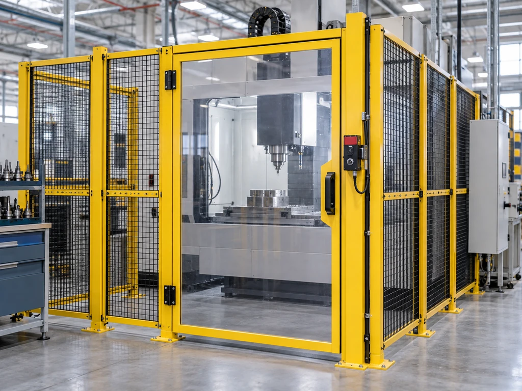
Interlocked Machine Guards combine a physical barrier with a safety-related control function so hazardous operation is inhibited when access is unsafe. The design must address the complete system, not just the door switch.
A sound design starts with tasks and hazards, then connects access time, stopping behavior, control reliability, restart control, and validation.
How Should Risks and Safety Functions Be Defined?
Risks and safety functions should be defined from foreseeable tasks, access routes, and hazardous states, with each function stating its required input, response, safe state, and performance target.
Hazards, Tasks, and Access Paths
Assess production, setup, cleaning, jam clearing, inspection, fault finding, and maintenance across the machine life cycle. For each task, identify the hazard, who can enter, which body part can reach it, how often access occurs, and whether energy or motion remains after a stop command.

Map every opening, removable panel, gate, and route around or under the guard. The choice among safety interlock switch families comes after this access analysis because actuator type, coding, and locking cannot correct an incomplete guard boundary.
Required Behavior for Closed, Open, and Locked Guards
Document permitted behavior for each state. A closed guard may permit a start only when the interlock and any lock-monitoring conditions are satisfied. An interlocked guard safety function must initiate the defined safe response when the guard opens during operation. Closing it should restore readiness, not automatically restart hazardous movement.
Where guard locking is used, distinguish guard closed, guard locked, and release permitted. The control system should authorize hazardous operation only from the required confirmed states and release the guard only after the defined safe-access condition exists.
Required Safety Performance
Assign the required performance from the risk assessment and any applicable machine-specific standard. ISO 13849-1 provides a method for safety-related control parts but does not assign a required Performance Level to a particular machine.
Define the entire safety function from sensor through logic to final switching elements. Architecture, component reliability, diagnostics, common-cause controls, software, wiring, and fault response all affect achieved performance; a switch rating alone is insufficient.
When Is Guard Locking Required?
Guard locking is required when a person could reach a hazardous condition before that condition has ended, or when release must wait for another verified safe state.
Stopping Time and Time to Reach the Hazard
Measure the worst-case time from the stop demand to cessation of the relevant hazard, including control response and mechanical run-down. Compare it with the shortest credible time from guard opening to hazard reach. If access can occur first, hold the guard locked until the hazard stops or redesign the distance and protective arrangement.
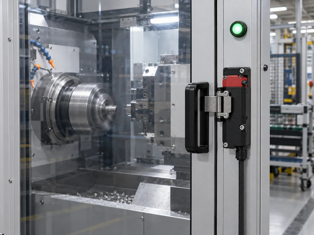
Use conservative measured stopping time under foreseeable load, speed, wear, and braking conditions. Recheck it after changes that can affect stopping performance.
Residual Hazards and Safe Release Conditions
Motion stopping may not remove pressure, heat, gravity, stored electrical energy, or suspended loads. Define release conditions in physical terms, such as verified zero speed, pressure below a specified safe limit, a supported axis, or completion of a controlled discharge.
Choose the locking principle and manual or emergency release behavior from the risk assessment. Loss of power must not create early access to a remaining hazard, and any escape provision must release a trapped person without authorizing machine restart.
How Should Access and Restart Risks Be Controlled?
Access and restart risks should be controlled by matching guard geometry and safety distance to partial-body reach, then adding escape, presence detection, and deliberate reset measures wherever whole-body entry is possible.
Partial-Body Access and Safety Distance
Use ISO 13857 for limb-reach distances and ISO 13855 for safeguard positioning based on approach and stopping time. Use the complete safety-function response and machine stopping time, not the drive’s nominal stopping time alone.
Check reach over, under, around, and through the barrier, including foreseeable body position and footholds. If the geometry changes or a larger opening is introduced, repeat the assessment rather than carrying over the previous distance.
Full-Body Entry, Escape, and Presence Detection
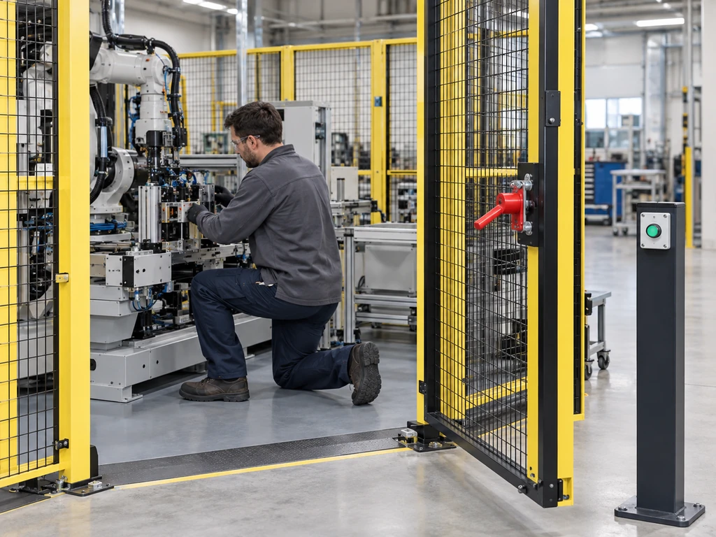
A closed gate cannot show that the safeguarded space is empty. Whole-body entry therefore requires measures such as an inside escape release, personal key or trapped-key control, presence sensing, or a controlled search-and-reset sequence, selected for the layout and task.
Presence detection must cover realistic hiding and shadow zones and remain active through the restart sequence. No person should depend on a normal access key or external power to escape.
Reset Location and Restart Prevention
Place the final reset outside the safeguarded space unless a validated multi-step system requires internal acknowledgment. Reset should acknowledge that protective conditions are restored; a separate start command should initiate hazardous operation.
If no single position provides a full view, use internal acknowledgment followed by external reset, or safety-rated presence detection. Evaluate foreseeable shortcuts, including reaching through mesh or using an unattended remote reset.
How Should the Safety-Related Control Chain Be Designed?
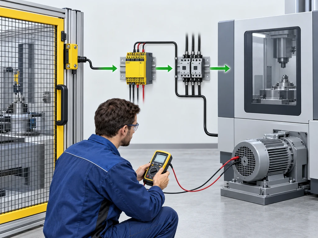
The control chain should detect guard and lock states independently where required, process them with safety-rated logic, and command monitored final elements that achieve the defined safe state under relevant faults.
Guard and Lock Status Detection
Select sensing principles and actuator coding for the risk of misalignment, tampering, contamination, and mechanical damage. Locking applications need clear evidence of both guard position and lock status; one signal should not be assumed to prove both unless the certified device architecture and system design support that conclusion.
A locking safety-door switch series offers separate configuration choices, but the exact ordered contacts, release mode, dimensions, ratings, and approval scope must be checked against controlled product documents.
Safety Logic, Diagnostics, and Fault Response
The safety relay or safety PLC should detect relevant shorts, channel discrepancies, contact faults, and invalid state sequences to the extent required by the chosen architecture. Define which faults cause an immediate stop, prevent the next start, or require a latched diagnostic and manual reset.
Diagnostics should make faults visible without enabling bypass. The related guide to guard-door locking and release checks extends the device-level considerations, but validation must use the final circuit and machine behavior.
Final Switching and Hazardous Function Control
Final elements may include contactors, safety drive functions, hydraulic valves, or pneumatic dump devices. Select them for the energy being controlled and monitor their state when fault detection is needed.
A stop command must produce the stated safe condition for every hazardous function covered by the guard. Feedback contacts or process sensors should confirm the relevant result where commanded state alone cannot reveal welded contacts, a stuck valve, or continued motion.
How Should the Completed Design Be Verified?
The completed design should first be verified against its safety requirements specification and then validated on the machine to confirm that each safety function reduces risk as intended. The validation plan should cover timing, state transitions, applicable faults, restart behavior, defeat resistance, and environmental suitability with documented acceptance criteria.
Stopping Time and Guard-Release Tests
Measure stopping time at the worst credible operating condition and from each relevant guard. Confirm that the lock cannot release before the safe-access condition and that measured margin remains adequate after applying the project’s tolerance and maintenance criteria.
Test normal stops, emergency stops, power interruptions, and monitored release conditions separately. One successful stop cannot establish performance across different loads, axes, or stop paths.
Fault, Reset, and Restart Tests
Test the faults required by the applicable standard and document the basis for every fault exclusion. Confirm the specified stop response, diagnostic indication, reset requirement, and inhibition of restart.
Open and close every guard in each permitted machine mode. Verify that reset cannot be initiated from inside the hazard zone and that guard closure, lock restoration, or power return alone does not start hazardous motion.
Defeat Resistance and Environmental Suitability
Inspect whether spare or mismatched safety-switch actuators, reachable fasteners, exposed sensors, or production pressure make bypass foreseeable. Reduce the incentive and opportunity through suitable coding, concealed or protected mounting, robust brackets, practical release timing, and supervision.
Verify enclosure rating, temperature range, vibration resistance, cable protection, cleaning chemicals, and contamination against the installed environment. Recheck alignment and stopping behavior after installation, then define periodic proof tests based on use and deterioration.
For component review, send XURUI the guard arrangement, required contact and release behavior, environmental limits, and applicable approval documents through the XURUI contact page. These details support model screening; the machine builder remains responsible for system validation.
FAQs
Can an Emergency Stop Replace an Interlocked Guard?
No. An emergency stop is a manually initiated complementary measure, while an interlocked guard controls access and prevents or stops hazardous operation when the guard state changes. The risk assessment may require both because they address different events.
Can a Standard Position Switch Replace a Safety Interlock?
Not by default. A standard position switch is acceptable only if its construction, actuation, fault behavior, installation, and integration satisfy the required safety function and performance; ordinary position indication provides no such assurance by itself.
What Should Happen to Guard Locking After Power Loss?
Power-loss behavior must preserve safe access and escape for the identified hazards. A power-to-release design may remain locked, while another locking principle may release; the design must coordinate residual-energy control, manual or emergency release, restart inhibition, and trapped-person escape.
When Should a Trapped-Key Interlocking System Be Used?
Use a trapped-key system when a defined key-exchange sequence can enforce isolation or access order, especially across remote disconnects, multiple doors, or full-body entry. The sequence, key uniqueness, escape arrangement, and energy-control procedure still require validation.
Does Opening an Interlocked Guard Make Maintenance Work Safe?
No. Opening the guard may stop normal hazardous operation, but maintenance can expose workers to unexpected startup, stored energy, gravity, pressure, or electrical hazards. Apply the energy-isolation procedure required in the installation country before work begins.
External Sources
- ISO 12100:2010 — Safety of machinery: Risk assessment and risk reduction
- ISO 14119:2024 — Interlocking devices associated with guards
- ISO 13849-1:2023 — Safety-related parts of control systems
- ISO 13855:2024 — Positioning of safeguards
- ISO 13857:2019 — Safety distances to prevent hazard zones being reached by upper and lower limbs
Industrial SPST toggle switch on a control panel](https://xuruiswitch.com/wp-content/uploads/2026/09/spst-toggle-switch-industrial-control-cover-300x225.webp)
SPST toggle switch product on a clean electronics workbench](https://xuruiswitch.com/wp-content/uploads/2026/09/spst-toggle-switch-cover-300x225.webp)