A selector switch is a manual control device that selects one of several defined circuit states or operating modes. Unlike a continuously variable control, it moves between discrete positions.
Understanding its mechanism, contact logic, actuator options, and ratings helps engineers and buyers specify a device that matches the control circuit rather than relying on appearance alone.
What Is a Selector Switch?
A selector switch lets an operator choose between functions such as On/Off, Forward/Reverse, Manual/Automatic, or Local/Remote. It commonly serves as a pilot device that commands a relay, contactor, or PLC input. It is not automatically suitable for switching a motor or other power load directly; that use requires an appropriate utilization rating.
Rotary knob and key-operated versions are common, but adjacent panel-mounted toggle controls can perform similar mode-selection tasks. The actuator style does not establish the internal circuit, so the contact diagram remains the controlling specification.
How Does a Selector Switch Work?
A selector switch works by converting movement of its operator into a defined combination of open and closed contacts. In many modular devices, turning the handle rotates a cam. The cam presses or releases plungers in contact blocks behind the panel, changing the connected control paths.
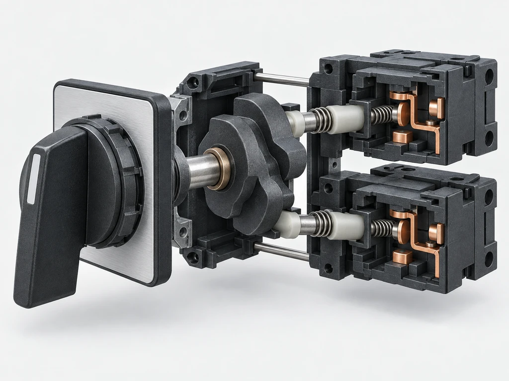
Detents hold maintained positions, while springs return momentary positions. Different cam and contact arrangements can produce different switching sequences, so use the contact chart for the exact model.
What Does a Three-Position Selector Switch Look Like?
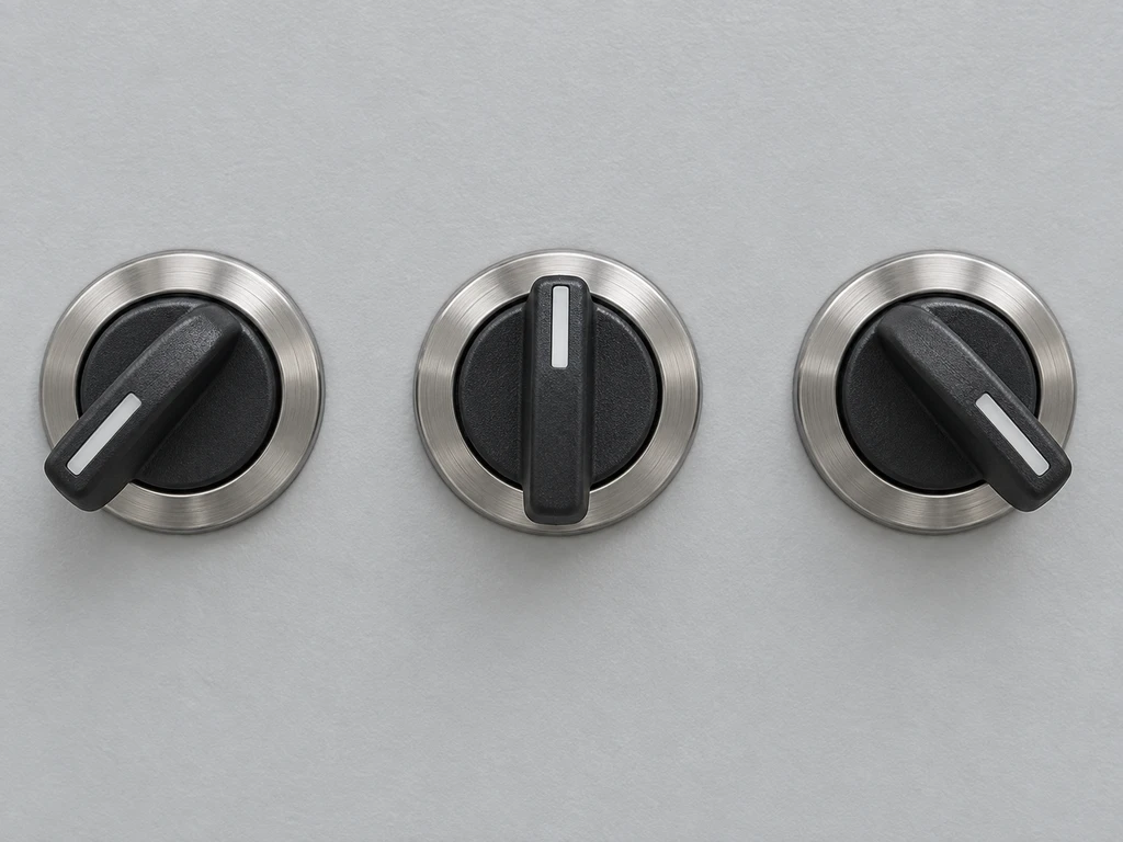
A three-position selector switch has three discrete positions, commonly arranged as left, center, and right. Its operator may be a handle, knob, or key. A legend plate may identify the positions as I–0–II, Forward–Off–Reverse, or Hand–Off–Auto. Key-operated and illuminated heads can have the same three-position arrangement.
Identify the three operator positions first, then check the model code, terminal markings, and contact diagram to determine the switching function. The center position is only Off when the specified contact chart shows the required circuits open there.
What Are the Different Types of Selector Switches?
Selector switches are classified by position count, operating action, and operator design. Each classification describes a different part of the device and must be combined with its contact logic.
Selector Switches by Number of Positions
Two-position models commonly select between two states, such as Off/On or Local/Remote. Three-position models add a center or third command, while four-position and multi-position designs support additional modes or instrument channels. For example, manufacturer specifications may offer the same three-position operator with different cams and contact blocks. Always select by the complete model code and contact chart.
Selector Switches by Operating Action
A maintained switch stays in the selected position. A momentary switch returns by spring action from one or more positions, and a mixed-action model combines maintained and spring-return positions. Specify the return direction explicitly because “three-position momentary” can describe several different operating patterns.
Selector Switches by Operator and Indication Type
Standard knobs provide unrestricted manual selection. Key operators restrict who can change a mode, but the key-removal positions must be specified. Illuminated operators add visual status when supplied by a separate lamp or LED circuit. An adjacent panel-mounted toggle switch family shows why the action, circuit form, terminals, and exact model must be checked separately.
Selector Switch Contact Logic and Position States
Contact logic defines which terminals conduct in every position. It is the bridge between the operator label and the behavior of the control circuit.
Two-Position and Three-Position Contact States
A two-position switch may alternate one common terminal between two paths, or independently open and close several contacts. A three-position switch can use the center as Off, as a third active mode, or as part of an overlapping sequence. Confirm every position with the manufacturer’s contact table instead of inferring the logic from the labels.
Normally Open and Normally Closed Contacts
A normally open contact is open, and a normally closed contact is closed, in the reference state defined by the manufacturer. On a maintained multi-position selector, “normal” can be unclear unless the reference position is identified. Use the NO and NC contact guide to interpret the reference state, then confirm the terminal numbers and contact diagram for the exact model.
Multiple Contact Blocks
Multiple contact blocks let one movement issue separate commands, such as enabling one circuit while disabling another. The blocks may be NO, NC, or changeover arrangements, depending on the device. Adding blocks increases available logic but does not combine their current ratings or guarantee simultaneous transfer.
The table below is a functional example. Contact A and Contact B are placeholders, not actual terminal designations.
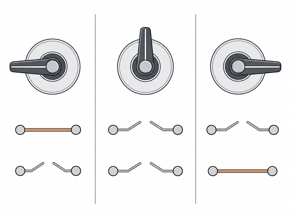
| Switch Position | Contact A State | Contact B State | Typical Mode |
| Left | Closed | Open | Hand/Manual |
| Center | Open | Open | Off |
| Right | Open | Closed | Auto |
The actual terminal assignment must match the switch diagram and the control design. Safety interlocks should remain effective in every mode.
Common Selector Switch Applications
The same operator can support different applications when its position sequence, contact arrangement, and load rating match the circuit.

Machinery and Motor Control
Two-position selectors can enable a machine or choose a direction, while three-position versions commonly command Forward–Off–Reverse. In motor-control circuits, the selector usually operates contactor coils or PLC inputs. Electrical and mechanical interlocking must prevent incompatible commands; a position label alone provides no interlock.
Pump, Fan, and HVAC Control
Hand–Off–Auto selection separates a local manual command, a stopped state, and control by a thermostat, pressure switch, level device, or building controller. The Hand position should not defeat required overload, limit, or safety functions. The position table must show which automatic input is enabled or isolated in each mode.
PLC and Automation Mode Selection
Local–Remote or Manual–Auto selectors send discrete mode signals to PLC inputs. Separate contacts can provide mutually exclusive input states or a positive state for each mode. The PLC program should detect invalid combinations and define behavior for an open wire, but software logic cannot correct an unsuitable contact sequence.
Electrical and Instrument Selection
Multi-position switches can select meter channels, test points, or control sources. Instrument circuits may require break-before-make or make-before-break sequencing. Current-transformer secondary circuits need purpose-designed switching arrangements, so a generic selector should not be substituted without reviewing the complete measurement circuit.
How to Choose a Selector Switch
Choose from the required circuit behavior outward: define each position and contact state first, then verify ratings, installation limits, operator features, and approvals for the exact catalog number.
Position Count, Operating Action, and Contact States
Write a position table showing every required command, whether each position is maintained or spring-return, and the state of every contact. This exposes ambiguous descriptions such as “three-position momentary.” For an adjacent lever-operated control example, the three-position momentary toggle guide explains how return patterns affect panel logic.
Contact Configuration, Load Type, and Electrical Ratings
Match the pole and contact arrangement to the circuit. The switch symbol guide explains SPST, SPDT, DPST, and DPDT notation; then compare the rating under the actual AC or DC load category, voltage, current, and duty. Resistive ratings may not cover the inrush or interruption demands of lamps, solenoids, contactor coils, or motors. If the datasheet omits the relevant load category, use an interposing device with verified ratings or request application data.
Panel Mounting, Terminals, and Environmental Protection
Check the specified panel cutout, anti-rotation feature, allowable panel thickness, rear mounting depth, and clearance for wiring. Match screw, quick-connect, solder, or PCB terminals to the assembly method. An enclosure rating applies only to the stated assembly and installation conditions; the operator, seal, enclosure, and unused openings all affect protection.
Operator Options and Certifications
Select a knob, key, or illuminated head according to access and status needs. Verify key-removal positions, legend visibility, illumination voltage, and replaceable components. Required marks or certifications must appear in documentation for the exact complete device or component configuration; a mark on another model in the series is insufficient.
For a model review, send the required position table, load details, and panel constraints when you contact the XURUI team. Those details allow a check against the requested circuit and installation conditions.
Frequently Asked Questions
Can a selector switch be used as an emergency stop?
No. A standard selector switch is not an emergency-stop device. Use a dedicated emergency-stop actuator and verify the complete safety function against ISO 13850, IEC 60947-5-5, and applicable local requirements.
Does a Selector Switch Consume Power?
Its mechanical contacts do not consume operating power in the way a load does, although closed contacts have small losses. An illuminated selector consumes power through its lamp or LED circuit, and any relay, contactor, or PLC input controlled by the switch has its own consumption.
Can I replace a two-position selector switch with a three-position model?
Yes, but only if the third position, contact sequence, ratings, panel fit, terminals, and control logic are all compatible. A mechanically fitting device may still create an unintended command, so update the schematic and test every state before service.
How Long Does a Selector Switch Last?
Service life depends on the model’s mechanical and electrical endurance ratings and on the applied load, switching rate, environment, and installation. Compare the rated mechanical and electrical cycles under the specified voltage, current, load type, and switching frequency.
Why does a selector switch become loose or fail to stay in position?
A loose mounting nut, worn detent or spring, damaged cam, vibration, or contamination can cause movement or poor position retention. Isolate the equipment, check the mounting and actuator mechanism, and replace the device if it cannot hold or reproduce each specified contact state. For selection, always confirm the position sequence, contact chart, load rating, and panel fit for the exact model.
External Sources
- Eaton: Understanding Pilot Devices
- ISO 13850:2015 — Safety of Machinery — Emergency Stop Function — Principles for Design
- IEC 60947-5-5:2026 — Electrical Emergency Stop Device with Mechanical Latching Function

Industrial SPST toggle switch on a control panel](https://xuruiswitch.com/wp-content/uploads/2026/09/spst-toggle-switch-industrial-control-cover-300x225.webp)
SPST toggle switch product on a clean electronics workbench](https://xuruiswitch.com/wp-content/uploads/2026/09/spst-toggle-switch-cover-300x225.webp)