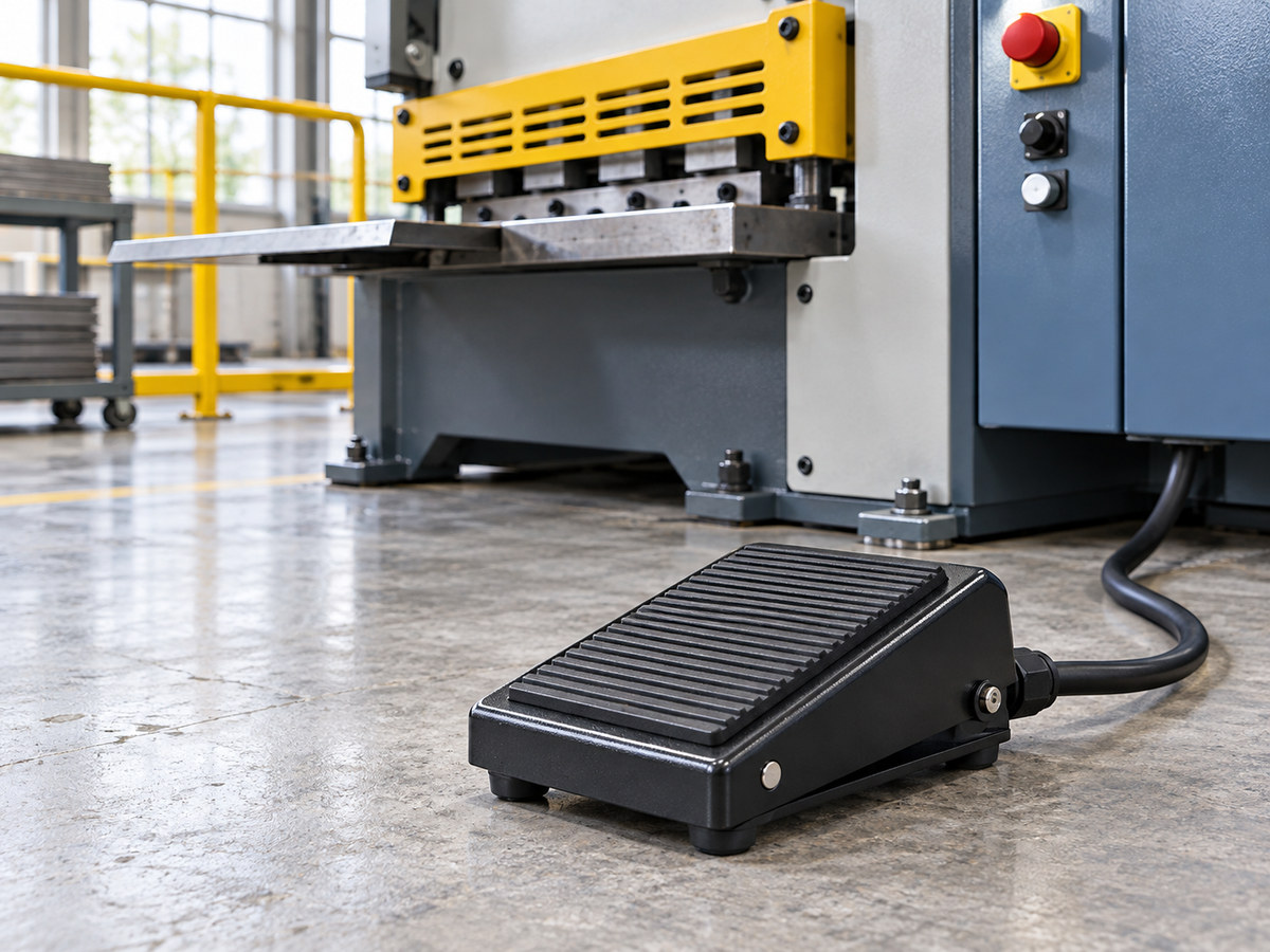
In manufacturing plants and metalworking shops, accidental machine cycling causes severe, preventable injuries. Hand controls often force operators to release workpieces during positioning. At the same time, unshielded or poorly matched foot pedals risk unintended cycling whenever an operator trips or steps away.
This selection guide details how to specify, size, and safeguard a momentary foot switch for industrial machinery. We examine spring-return mechanics, contact ratings, protective guarding, housing durability, and OEM integration so engineering teams choose the right pedal for dependable control.
How Momentary Spring Return Mechanics Differ From Maintained Action
Industrial foot switches use two core operating modes based on their internal return mechanism. Selecting the wrong action compromises operator safety and process repeatability.
| Operation Type | Actuator Mechanism | Contact State on Release | Primary Safety Role | Typical Machinery Applications |
|---|---|---|---|---|
| Momentary (Spring Return) | Internal compression spring resets treadle immediately | Contacts revert to normal state upon foot removal | Deadman control, single-cycle press initiation, jog feeding | Power presses, spot welders, pipe benders, shearers, riveters |
| Maintained (Latching / Bistable) | Mechanical detent latch holds treadle down | Contacts remain locked until second foot press | Continuous process activation without holding pedal down | Conveyor lines, vacuum pumps, industrial sewing, shop lighting |
Spring-Return Actuation and Contact State Behavior
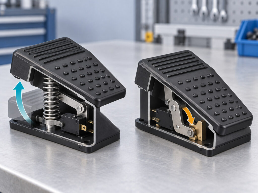
Momentary foot switches use internal compression springs that push the treadle back to resting position the moment foot pressure lifts. Inside the housing, this mechanical reset drives a snap-action micro switch that opens normally open contacts or closes normally closed contacts.
Because circuit continuity requires active operator presence, the switch cannot remain energized through momentum. This immediate reset provides a fundamental safeguard for machines where unexpected motion could injure personnel or wreck tooling.
Deadman Safety Control and Cycle-Start Functions
On hazardous equipment, momentary foot switches serve as active deadman controls. When an operator runs a hydraulic shear, press brake, or pneumatic riveter, lifting their foot cuts control power or signals a safety controller to halt motion instantly.
For single-stroke stamping cycles, control logic uses a momentary pulse to initiate one cycle while anti-repeat circuitry ignores held-down pedals. This setup ensures that an operator who trips, falls, or pulls back from a jam cuts electrical drive simply by lifting their foot.
Selecting Contact Configurations and Electrical Load Ratings
Matching internal contact blocks to your control circuit prevents premature contact wear, welding, and false PLC signals. Industrial machinery requires clear separation between low-voltage digital signaling and high-current line switching.
Matching Normally Open and Normally Closed Contacts to Control Circuits
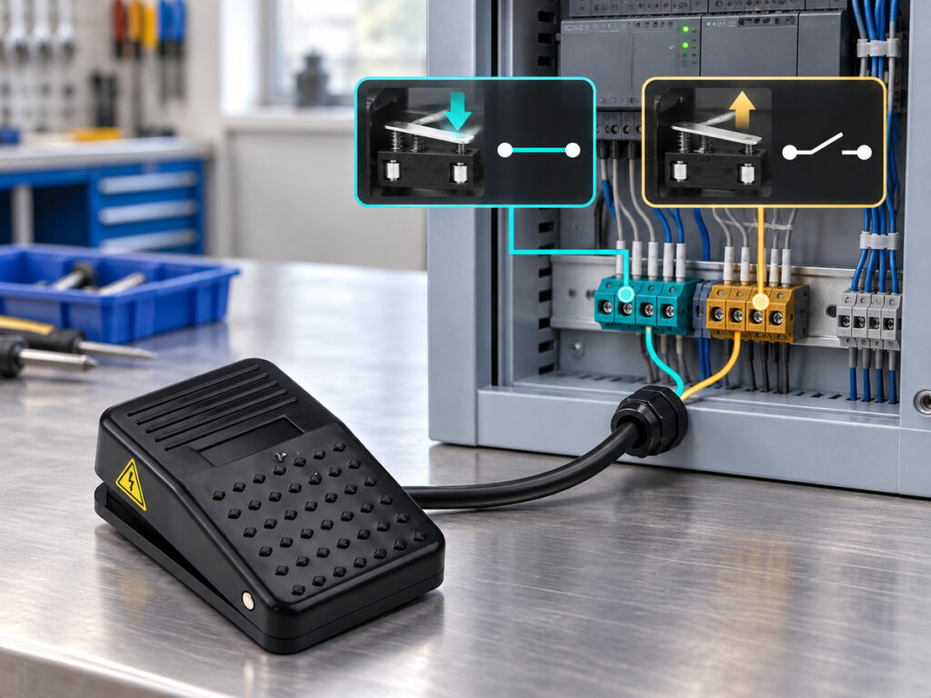
Most momentary foot pedals use a single-pole double-throw contact block with normally open and normally closed terminals sharing a common pin. Circuit designers select contact paths based on required machine behavior:
- Normally open (NO) circuits: Pressing the treadle closes the circuit to start a cycle, trigger a clamp, or feed stock.
- Normally closed (NC) circuits: Removing foot pressure breaks power, providing a fail-safe stop circuit for web tensioning or safety interlocks.
Reviewing NO and NC pedal switch schematics clarifies how internal contact blocks map to PLC input channels and field terminations. For systems requiring separate monitoring channels, dual-pole double-throw configurations supply isolated electrical circuits that satisfy higher functional safety requirements.
Handling Inductive Inrush Currents and Sizing Interposing Relays
Standard micro switches inside foot pedals handle resistive loads up to 10A or 15A at 250VAC, but inductive loads require substantial derating. Electric motor starters, hydraulic solenoid valves, and electromagnetic brakes draw inductive inrush currents five to ten times their steady operating current, followed by severe voltage spikes during contact opening.
These arc events erode silver contacts, increase resistance, and weld contact tips together. When switching inductive loads or motors above fractional horsepower ratings, route the foot switch through an interposing contactor, motor starter, or solid-state relay instead of carrying full line current through the pedal.
Evaluating Housing Materials and Mechanical Impact Protection
Plant floors subject foot switches to falling workpieces, scrap, and heavy boots. Selecting the correct enclosure material prevents structural cracking and internal mechanical binding.
Comparing Die-Cast Metal and Industrial Plastic Enclosures
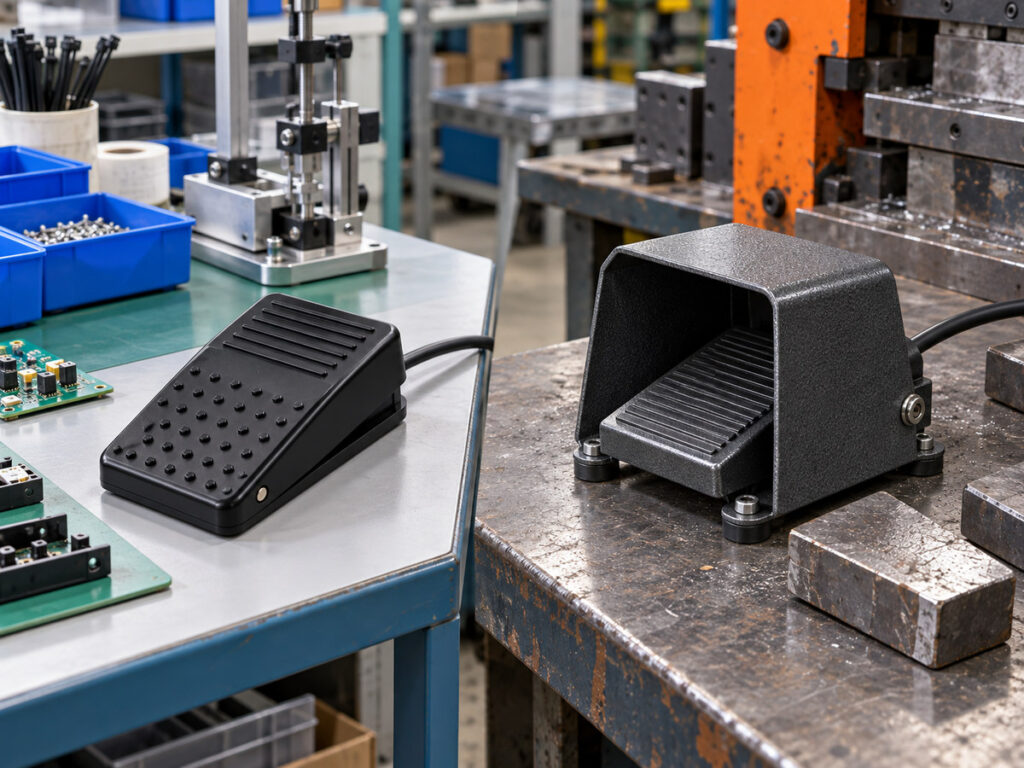
Demanding production environments such as stamping plants, foundries, and fabrication shops require die-cast aluminum alloy or zinc alloy housings. Metal enclosures absorb direct blows from dropped tools, resist deflection under operator weight, and provide the mass needed to keep the pedal stable on concrete floors.
For lighter duties such as electronics assembly, packaging lines, and laboratory stations, engineering polymers like flame-retardant ABS or reinforced nylon reduce unit weight while resisting washdown chemicals and light corrosion.
Preventing Pedal Fractures Under Repeated Heavy Stomping
Operators frequently stomp foot switches with excessive force during fast assembly shifts. Over millions of cycles, repeated impact stress concentrates on the pedal hinge pin, internal stops, and switch operating levers. In lightweight commercial pedals, high overtravel forces bend linkages or fracture the internal micro switch body.
Understanding these high-stress points helps maintenance teams in preventing foot switch failure before worn return springs or cracked linkages cause unscheduled downtime. Industrial-grade foot pedals build hardened mechanical stops directly into the casting to absorb excess force before it reaches the electrical block, preventing pivot distortion and fatigue failure across demanding shifts.
Ingress Protection and Environmental Sealing for Factory Floors
Fluid contamination and particulate matter cause most floor-level electrical failures. Proper sealing protects insulation resistance and keeps internal switch mechanisms dry.
Selecting Ingress Protection Ratings for Coolant and Dust Resistance
Because foot switches sit at floor level, they face settling dust, metal swarf, lubricants, and washdown water. For dry assembly areas, an IP40 or IP54 housing keeps out larger debris and airborne dust.
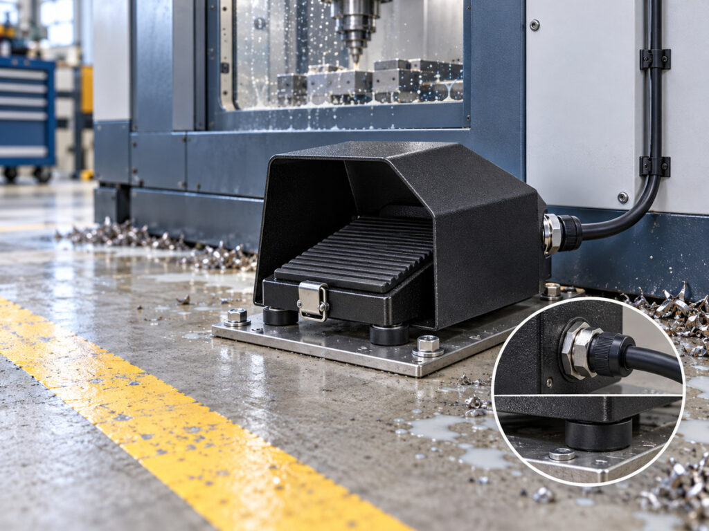
In machining cells exposed to water-soluble coolants, wet grinding debris, or food-grade washdowns, specify an IP65 or IP67 enclosure. Specifying appropriately sealed industrial foot switches prevents coolant ingress and ensures reliable electrical insulation across harsh shop environments. These sealed units use synthetic rubber perimeter gaskets between the top housing and base plate, combined with a rubber bellow sealing the internal actuator shaft against fluid ingress.
Securing Flexible Cord Strain Relief and Cable Glands
Floor cables face continuous abuse from foot traffic, carts, and equipment repositioning. A simple rubber grommet allows fluids to enter the housing while letting cable tension pull directly on screw terminals.
Industrial momentary foot switches use threaded conduit entries, typically PG or metric threads, fitted with liquid-tight cable glands. Pairing these glands with oil-resistant flexible cord, such as SOOW or rubber-jacketed cable, seals the wiring chamber against moisture while isolating electrical connections from external cord pulls.
Operator Ergonomics, Guarding, and Anti-Trip Safety Features
Physical guarding separates safe industrial foot controls from hazardous open pedals. Proper ergonomic design and accidental-trip prevention protect workers while sustaining production rates.
Installing Protective Hoods and Safety Latches to Stop Accidental Actuation
An unshielded pedal introduces immediate danger because a dropped metal blank, fallen hand tool, or stumble can depress the treadle and cycle the machine. Machinery safety standards, including OSHA regulations for mechanical power presses, require protective hoods over foot controls on hazardous equipment. Heavy metal hoods arch over the treadle, providing clearance for steel-toed boots while shielding the pedal from falling debris.
Reviewing industrial foot switch safety certifications ensures that pedal guarding and electrical assemblies satisfy regional machinery directives and OSHA workplace mandates. For high-risk machinery, an integrated anti-trip safety foot latch adds a mechanical barrier that forces the operator to slide their foot under the latch to release the pedal before pressing downward.
Stabilizing Treadle Pads and Preventing Floor Slip
A pedal that shifts across the floor forces operators to reach awkwardly, impairing balance and slowing work. Heavy industrial foot switches incorporate high-friction rubber feet on the base casting to resist sliding across smooth or oily concrete. The upper treadle surface features raised ribs or textured waffle patterns that maintain boot grip even when wet.
For permanent machine stations, using integrated mounting holes to anchor the pedal base directly to the shop floor ensures stable, repeatable positioning across all production shifts.
Specifying Xurui XF Series Foot Switches for OEM Machinery
Sourcing foot switches for production machinery requires proven mechanical life, reliable switching, and flexible manufacturing options. Xurui manufactures the XF Series to meet rigorous industrial control standards.
| Series Model | Housing Material | Pedal Guard Style | Standard Contact Form | Electrical Rating | Typical Machinery Applications |
|---|---|---|---|---|---|
| XF-01 | Engineering polymer | Open treadle (compact) | 1NO+1NC snap action | 10A at 250VAC | Assembly benches, textile equipment, packaging tables |
| XF-1 | Die-cast aluminum alloy | Open treadle (low profile) | 1NO+1NC snap action | 10A at 250VAC | Woodworking tools, testing stations, light machine tools |
| XF-2 | Die-cast aluminum alloy | Full protective metal hood | 1NO+1NC or 2NO+2NC | 10A at 250VAC | Stamping presses, hydraulic riveters, shears, pipe benders |
| XF-3 | Die-cast aluminum alloy | Full protective hood with safety latch | 1NO+1NC snap action | 10A at 250VAC | Heavy metalworking presses, cutting equipment, welding cells |
| XF-J01 | Reinforced polymer | Shielded low-profile pedal | 1NO or 1NC micro switch | 10A at 250VAC | Medical devices, laboratory gear, light processing equipment |
Selecting Standard and Heavy-Duty XF Models for Production Equipment
The XF Series Foot Switch line provides multiple enclosure sizes, guard configurations, and contact blocks to match equipment needs. For standard automated machinery with low impact risks, models like the XF-01 and XF-1 deliver responsive control in a compact footprint.
For severe factory environments involving metal shearing, punching, and automated welding, heavy-duty models like the XF-2 and XF-3 provide die-cast metal enclosures with full protective hoods. Standard electrical ratings support loads around 10A at 250VAC, with insulation resistance rated at 100 megaohms or higher at 500VDC and contact resistance kept below 25 milliohms for clean, consistent switching.
Verifying Anti-Breakage Construction and Ordering OEM Samples
A key structural feature of the Xurui XF Series is its patented anti-breakage construction. This internal linkage design reinforces the mechanical interface between treadle and micro switch, routing excessive stomp force through structural load paths rather than the switch mechanism.
Xurui supports machinery OEMs with custom cable lengths, tailored contact arrangements, and private labeling backed by ISO 9001 quality management and TUV product certifications. Equipment designers can request physical evaluation samples to verify treadle resistance, return spring force, and enclosure fit on production prototypes.
Frequently Asked Questions
How Can a Momentary Foot Switch Maintain Continuous Machine Operation After Release?
A momentary foot switch maintains continuous machinery operation after release by interfacing with a 3-wire motor control circuit or a programmable logic controller. In an electromechanical circuit, pressing the normally open pedal energizes a magnetic motor starter coil, which closes an auxiliary seal-in contact wired in parallel with the foot switch to maintain power. In automated systems, the switch sends a single digital pulse to a PLC input that latches an internal logic bit until a separate stop button or safety interlock opens the circuit.
When Does Industrial Machine Safety Require a Full Foot Guard Hood Over the Pedal?
Machine safety standards require a full protective foot guard hood whenever unintended pedal actuation could expose operators to point-of-operation hazards, mechanical pinch points, or dangerous tooling. Regulations like OSHA 1910.217 for mechanical power presses and ANSI B11 standards mandate protective hoods over foot controls to prevent accidental cycling from dropped parts, falling tools, or inadvertent operator contact. Equipment with exposed blades, rotating cutters, or closing dies must always use guarded foot pedals.
What Causes a Momentary Foot Switch to Stick Down or Return Sluggishly?
Sluggish pedal return or mechanical sticking usually results from particulate buildup in the hinge pivot or internal return spring degradation. In manufacturing environments, metal dust, sawdust, or dried cutting fluid residues accumulate around the pivot pin and treadle gaps, creating mechanical friction that overcomes the spring return force. Less frequently, severe operator stomping or corrosive fumes fatigue or corrode the internal compression spring, reducing its reset force and requiring pivot cleaning or spring replacement.
XURUI Engineering Team
Industrial SPST toggle switch on a control panel](https://xuruiswitch.com/wp-content/uploads/2026/09/spst-toggle-switch-industrial-control-cover-300x225.webp)
SPST toggle switch product on a clean electronics workbench](https://xuruiswitch.com/wp-content/uploads/2026/09/spst-toggle-switch-cover-300x225.webp)