
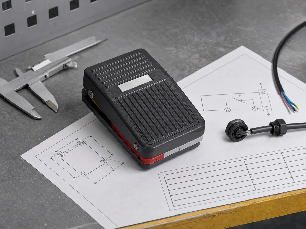
A foot switch symbol shows the pedal contact state at rest and after an operator presses it. Read that state first, then verify the device tag, terminal diagram, and exact model documentation before wiring a circuit or ordering a replacement.
In a schematic, normal means no operator presses the pedal. It does not mean the circuit is de-energized. A normally open contact is open at rest and closes when an operator presses the pedal. A normally closed contact conducts at rest and opens when an operator presses the pedal.
What Does a Foot Switch Symbol Show?
A foot switch symbol shows electrical function, not a complete product specification. The drawing may show an NO contact, an NC contact, a changeover contact, or a mechanically linked contact group. A tag such as FS1 or S12 identifies the pedal assembly that owns the contact.
Schematic drawings show the contact in its rest state. A gap means the path does not conduct in that state. A continuous line means it conducts. The drawing may also show a pedal actuator mark, terminal number, or cross reference to another sheet. Those details identify the device, but the rest-state contact logic determines how the control path behaves.
How Do NO and NC Pedal Contacts Change When Pressed?
Pressing the pedal changes the contact state shown on the unactuated schematic. Confirm the required rest state before selecting an NO, NC, or combined contact arrangement.
| Contact arrangement | Pedal at rest | Pedal pressed |
|---|---|---|
| 1NO | Circuit open | Circuit closed |
| 1NC | Circuit closed | Circuit open |
| 1NO+1NC | NO circuit open and NC circuit closed | NO circuit closed and NC circuit open |
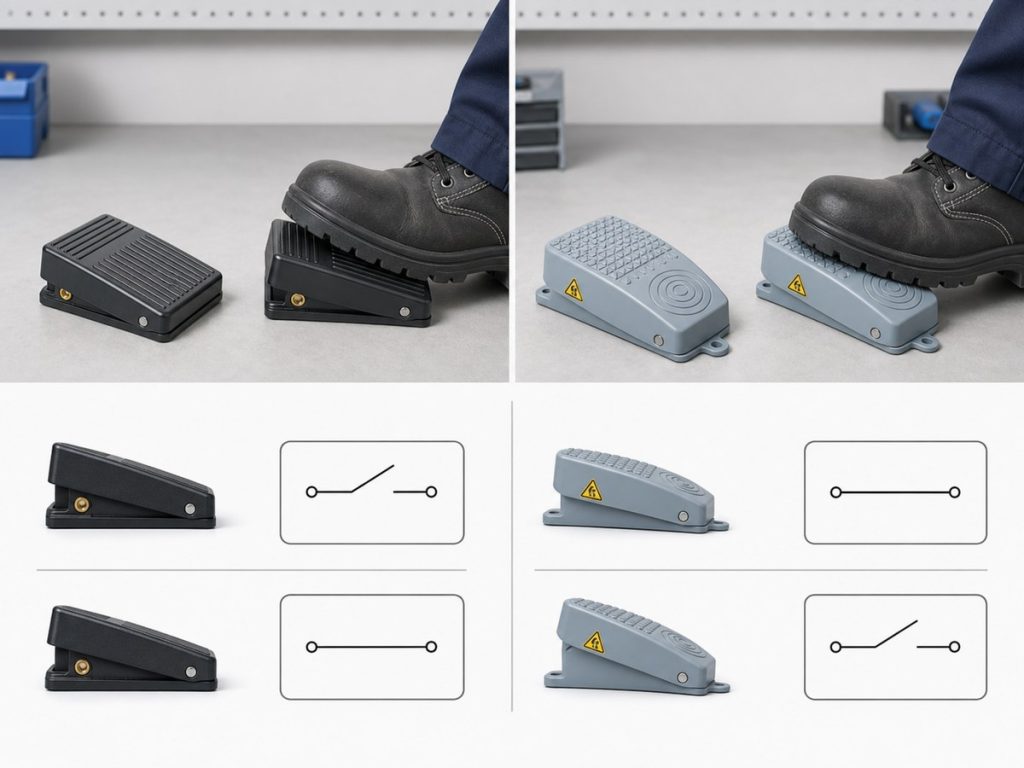
1NO Contact Operation
A 1NO foot switch has one normally open contact. The control path remains open until the operator presses the pedal, when the two terminals connect. This arrangement suits a command that must appear only after the pedal moves.
The symbol does not show whether the pedal returns when released. A momentary pedal and a maintained pedal can both use a 1NO contact. Confirm the action type in the product documentation.
1NC Contact Operation
A 1NC foot switch has one normally closed contact. The circuit is continuous while the pedal is at rest, then opens when the operator presses the pedal. The control design must expect that reversed rest condition.
Before replacing an installed pedal, compare its circuit state with normally open and normally closed switch behavior. A housing label that only says “foot switch” does not identify the contact form.
A 1NO+1NC Contact Set
A 1NO+1NC set has two contact circuits driven by the same pedal. At rest, the NC circuit is complete and the NO circuit is open. When the operator presses the pedal, the NC circuit opens and the NO circuit closes.
This arrangement is different from a 1C, or changeover, contact. A 1C contact has one common terminal that transfers between NC and NO. A 1NO+1NC set can use two separate contact circuits that share only pedal movement. Check the terminal diagram before treating either arrangement as a three-terminal changeover contact.
How Do You Read a Foot Switch Schematic?
Read a foot switch schematic from the control function outward. Start with the pedal at rest, follow the path through the contact, then use the device tag and terminal information to connect the symbol to the installed device.
Tracing the Control Path
Start at the documented source or control input and follow each conductor to the foot switch contact. Determine whether the path must be continuous at rest or only after an operator presses the pedal. Then follow the other side of the contact to the PLC input, relay coil, contactor control circuit, or other documented load.

This method prevents a common mistake: reading an open contact as a fault when the drawing shows an unpressed 1NO pedal. If a verified continuity test does not match the drawing, isolate the equipment under the site’s approved electrical safety procedure, then check the terminal mapping and the pedal action before changing wires. The same check can help when investigating foot switch failure causes, because a mechanical or wiring fault can resemble an incorrect contact state.
Following Device Tags and Cross References
Use the device tag to find every contact that belongs to the pedal. A drawing may identify a foot switch as FS1, then show its contacts on different sheets or grid locations. A cross reference can point to a related contact, coil, terminal block, or field device.
Do not assume nearby symbols belong to the same pedal. Match the complete tag, drawing reference, and bill of materials or wiring schedule. A multi-function pedal needs a defined contact function for each circuit. That record is also needed when selecting dual or triple pedal configurations.
Checking the Terminal Diagram
The schematic gives the logical function. The terminal diagram identifies the physical terminals or cable cores that provide it. Read both before installation or replacement.
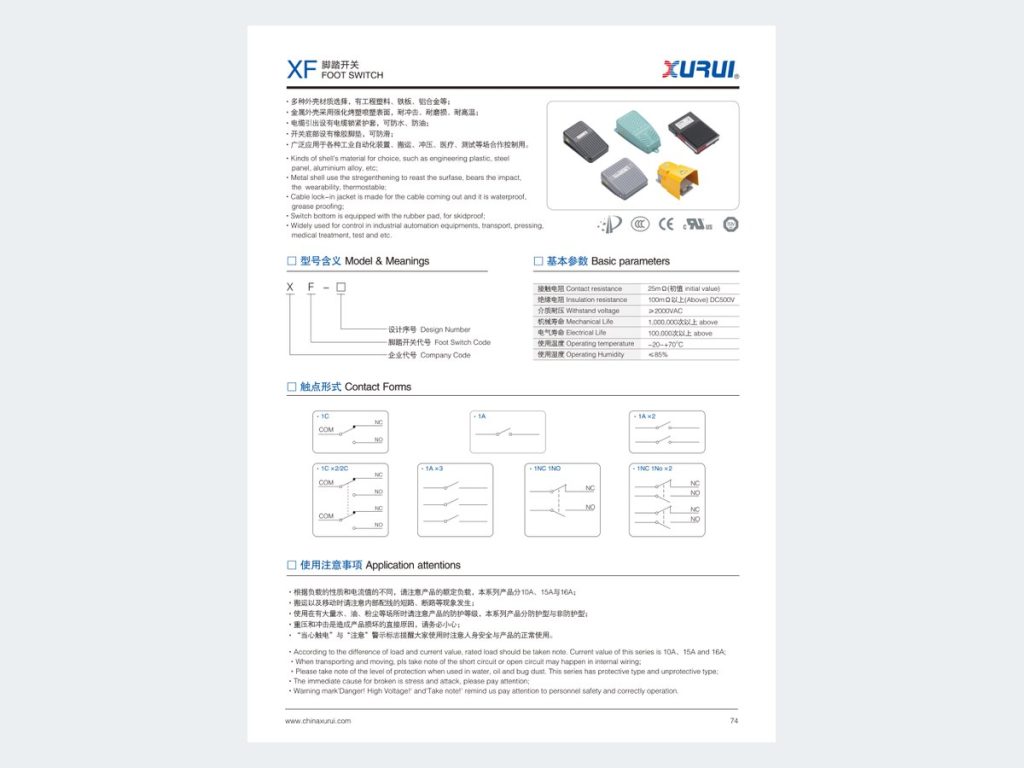
For a three-terminal changeover contact, COM is the shared terminal. The terminal diagram must identify COM, NC, and NO for the specified device. A simple 1NO or 1NC contact may have only two terminals and no COM terminal. A 1NO+1NC arrangement may instead use separate terminal pairs.
Terminal numbers, wire colors, and connector pin positions depend on the model. Use the exact drawing for the ordered part, especially when replacing a pedal with a cable assembly or more than one contact circuit.
Which Details Cannot Be Read From a Foot Switch Symbol?
A foot switch symbol cannot replace the data sheet, outline drawing, or approved ordering code. It states circuit function and normal contact state only.
Momentary or Maintained Pedal Action
Technical documentation must state whether the pedal returns after release or remains in its selected state. Specify momentary or maintained action separately, then confirm that the circuit needs the resulting state change.
Electrical Duty
Electrical duty requires a separate rating for voltage, current, AC or DC use, load type, motor inrush capability, and electrical life. A contact diagram does not prove that a pedal can switch a specific motor or load directly. Confirm the exact model rating and the circuit’s load requirements.
Mounting and Cable Entry
An outline drawing identifies pedal dimensions, guard shape, mounting holes, cable length, cable exit direction, connector, and terminal access. These details determine whether a replacement fits the machine and whether the cable reaches the enclosure without strain.
Environmental Exposure
The product documentation must identify any ingress rating, temperature limit, oil exposure, washdown suitability, and protection supplied by the installation. Match these conditions to the documented rating of the exact product version, not to a general foot switch family description.
How Should Buyers Document a Foot Switch Requirement?
Buyers should document the circuit state, installation, and operating environment before naming a foot switch model. Specify what happens when the pedal is released and pressed, the required contact arrangement, such as 1NO, 1NC, 1NO+1NC, or 1C, the number of independent pedals, and whether the action is momentary or maintained.

Include the control circuit, voltage, current, load type, and whether the pedal drives a control input or a separately rated switching device. Attach the schematic, terminal diagram, part number, wire or connector details, cable length, mounting dimensions, guard requirement, environmental exposure, required documents, and expected order quantity. For a new or replacement request to Xurui, this information lets the supplier compare the required circuit function with the correct ordering code.
When Is the XF Series Foot Switch a Documented Match?
The XF Series Foot Switch is a documented match only when the selected ordering code meets the required contact form, electrical duty, pedal action, mounting details, and environmental rating. An NO or NC request alone does not prove that an XF version fits the circuit. The XF catalog includes 1A normally open, 1C changeover, and 1NC+1NO contact arrangements. XF-01, XF-1, XF-2, and XF-3 are listed with 1C contacts, a 10A/250VAC rated load, and IP54 protection. Those values apply only to the named catalog entries.
Start with the Foot Switch collection to confirm that the product family fits the application. Then use the XF Series Foot Switch documentation to match the contact state, load, environment, and mounting details to the ordering code. The schematic, terminal requirement, cable details, and mounting drawing must agree before ordering a replacement.
Frequently Asked Questions
Are IEC and ANSI Foot Switch Symbols the Same?
Not necessarily. IEC and ANSI or IEEE drawing systems can use different graphic conventions and reference designations, although both can express the same NO or NC contact logic. Follow the standard and legend named on the drawing, then verify the released and pressed states from the contact path.
Can an NC Foot Switch Replace an NO Foot Switch?
No, not as a direct replacement. An NC foot switch reverses the circuit state at rest, which can change PLC logic, relay behavior, or diagnostic expectations. Replace it only after the responsible engineer checks and tests the required control behavior.
How Can I Identify COM, NO, and NC on an Unlabeled Foot Switch?
First isolate the foot switch from all power and connected circuits under the site’s approved electrical safety procedure. On a three-terminal changeover contact, COM has continuity with NC at rest and with NO when pressed. A two-terminal 1NO or 1NC contact has no COM terminal, so use the exact terminal drawing or a controlled continuity test instead of assigning labels by terminal position.
Do NO and NC Contacts Change State at Exactly the Same Time?
Do not assume they do. A schematic shows the required logical states, not contact travel, bounce, or make-and-break timing. If timing affects a control or safety function, request the relevant data from the manufacturer or test the exact model in the intended circuit.
Can a Foot Switch Switch a Motor Directly?
Only when the manufacturer documents that motor duty for the exact pedal and the complete circuit supports it. Check motor voltage, current, inrush conditions, and the pedal’s rated switching capability. When the documentation does not confirm that capability, use the foot switch as a control input for a separately rated switching device.
XURUI Engineering Team






