
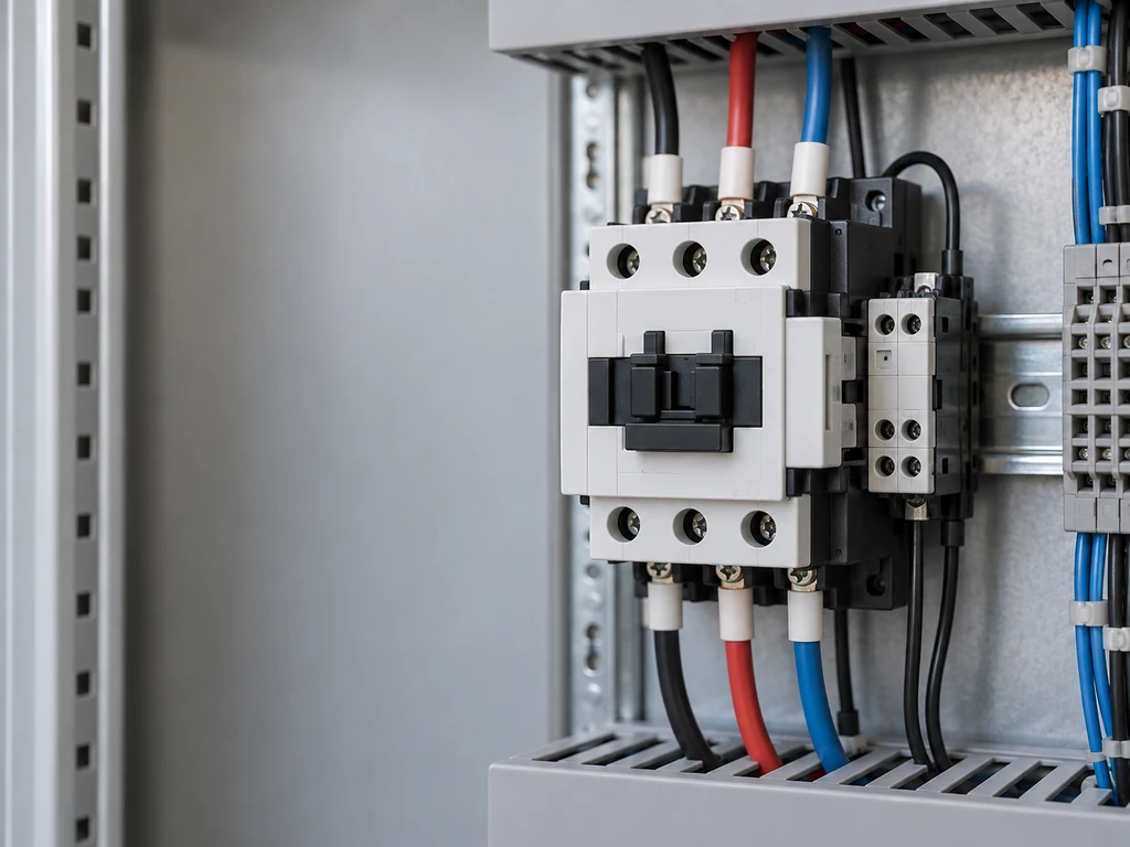
A contactor is an electrically controlled switch that repeatedly connects and disconnects a power circuit. It lets a low-power control signal operate motors, heaters, lighting, and other higher-current loads.
Its electromagnetic system moves the contacts, while springs and arc-control components support reliable opening. Understanding these parts helps engineers distinguish switching functions from circuit protection and select the right ratings.
What Is an Electromechanical Contactor?
An electromechanical contactor uses an energized coil and a moving armature to operate power contacts. Unlike a manual switch, it can respond to a push button, programmable logic controller, thermostat, timer, or other control device.
The electromagnetic actuator separates the control function from the power circuit, but the contactor’s insulation rating and suitability for isolation require model-specific verification. A contactor also provides no inherent short-circuit protection and may require an overload relay when controlling a motor.
Contactors switch mechanically. For silent or frequent electronic switching, solid state relays are a separate alternative that requires thermal and circuit-protection review.
What Are the Main Parts of a Contactor?
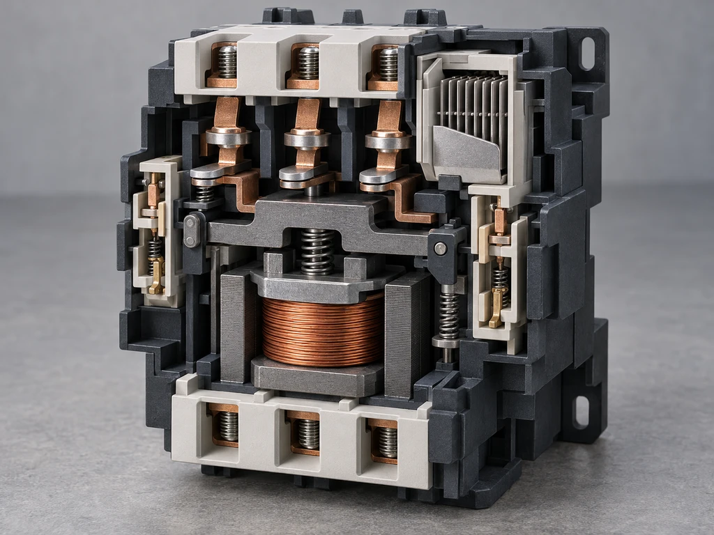
The main parts are the electromagnetic system, contact system, return springs, arc-suppression components, and insulated enclosure. Each part controls mechanical movement, current flow, arc management, or separation from accessible surfaces.
Electromagnetic System
The electromagnetic system normally includes a coil, stationary core, and movable armature. Applying the coil’s rated control voltage creates magnetic flux and pulls the armature toward the core. AC designs may include a shading ring to reduce chatter as the magnetic field passes through zero.
Main and Auxiliary Contact System
Main contacts carry the controlled load current. They are commonly normally open, so energizing the coil closes the power circuit.
Auxiliary contacts carry lower-current control or signaling circuits. Normally open and normally closed contacts can provide interlocking, seal-in control, status indication, or controller feedback. Their ratings are separate from those of the main contacts.
Return Springs
Return springs hold or drive the contactor toward its de-energized state. When magnetic force falls below spring force, the springs separate the main contacts and restore the auxiliary contacts. Weak, broken, or obstructed springs can cause slow opening or an incorrect rest position.
Arc Suppression System
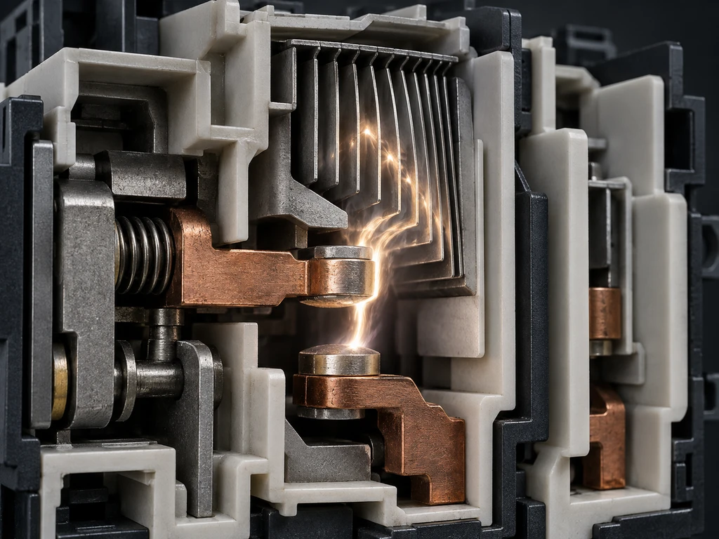
An arc can form across the widening contact gap when the contacts open. Arc chutes, splitter plates, contact geometry, and rapid separation help stretch, divide, cool, and extinguish it. The required arrangement depends on the current type, circuit voltage, and load.
Enclosure and Insulation Components
The enclosure supports the terminals, keeps internal parts aligned, and limits access to energized components. Molded barriers maintain creepage and clearance between poles and between control and power circuits. Safe application therefore depends on the enclosure condition, installation environment, and product insulation ratings.
How Does a Contactor Work?
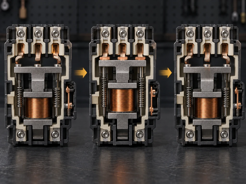
A contactor converts electrical energy in its coil into mechanical movement. This movement changes the main and auxiliary contact states. Removing coil power allows the return mechanism to restore the normal state.
Coil Energization
When the specified control voltage reaches the coil, current creates a magnetic field in the core. The coil must match the control supply’s AC or DC type, voltage, and frequency where applicable. Undervoltage can prevent full pickup and cause chatter, while excessive voltage increases coil heating.
Armature Movement
Magnetic attraction pulls the movable armature toward the stationary core. A linkage transfers this motion to the contact carrier. The armature must seat fully; contamination, mechanical damage, or low coil voltage can prevent complete travel.
Armature Movement and Contact State Changes
As the armature moves, normally open main contacts close and normally closed auxiliary contacts open, depending on the contact configuration. Other auxiliary contacts change state at defined points in the stroke. Contact pressure after closure reduces resistance and helps keep the power contacts stable.
Contact Opening and Spring Return
Removing coil power collapses the magnetic field. The return springs move the armature and contact carrier back, opening the main contacts and restoring the auxiliary contacts. The arc must then extinguish before the contact gap can interrupt the circuit.
How Is a Contactor Different From Related Switching and Protection Equipment?
A contactor is mainly a remote power-switching device, not a complete protection system. Related equipment may operate in the same circuit, but each device has a different function.
| Equipment | Primary Function | Typical System Role | Protection Provided |
| Contactor | Repeated remote switching | Connects or disconnects a load on command | None unless protection is specifically integrated and rated |
| Control relay | Switches low-power circuits | Logic, signaling, and interlocking | Generally none |
| Overload relay | Detects sustained motor overload | Trips the contactor control circuit | Motor overload protection; functions vary by model |
| Circuit breaker | Interrupts specified overcurrent faults | Feeder or branch-circuit protection | Rated overcurrent protection; motor-circuit coordination requires separate verification |
| Disconnect switch | Provides a defined isolation function | Maintenance isolation | Usually none unless combined with fuses |
| Solid state relay | Switches loads electronically | Silent or frequent load control | Generally none; coordinated protection is required |
A solid state relay selection guide explains how switching method, heat dissipation, and off-state leakage affect an electronic switching application.
What Ratings Matter When Selecting a Contactor?
Selection starts with the load, operating voltage, coil supply, switching duty, and installation conditions. A current rating without its utilization category and operating voltage is not enough.
Load Type and Utilization Category
Load behavior determines the current and arc stress during closing and opening. A resistance heater, squirrel-cage motor, transformer, capacitor bank, and discharge lamp can place different demands on the same contacts.
Under IEC 60947-4-1, AC-1 applies to non-inductive or slightly inductive loads, while AC-3 covers starting and stopping running squirrel-cage motors. Select the contactor by its load category, operating voltage, and current rating.
Rated Operating Voltage and Current
The rated operational voltage and rated operational current apply together under stated load and duty conditions. The contactor must carry and interrupt the required current at the system voltage under the assigned utilization category.
For motors, use the manufacturer’s motor-power table only when its voltage, frequency, utilization category, and operating conditions match the installation. Short-circuit coordination must also be checked with the specified protective device.
Coil Voltage
Coil voltage must match the control supply, including AC or DC type and AC frequency. Check the allowed pickup and holding ranges when voltage variation is expected. An incorrect supply can prevent closing, cause chatter, or overheat the coil.
Switching Frequency and Duty Cycle
Switching frequency affects contact erosion, coil temperature, and mechanical life. Confirm the permitted operations per hour, electrical life at the actual load, mechanical life, and assigned duty.
Frequent heater switching may favor an SSR. The XSSR-W15 series can be evaluated after confirming its switching rate, thermal design, and protection requirements.
What Are Contactors Used For?
Contactors are used when a control signal must switch a power load repeatedly or from a remote location. The selected device must match the load’s starting current, operating current, voltage, and switching pattern.
Motor Control
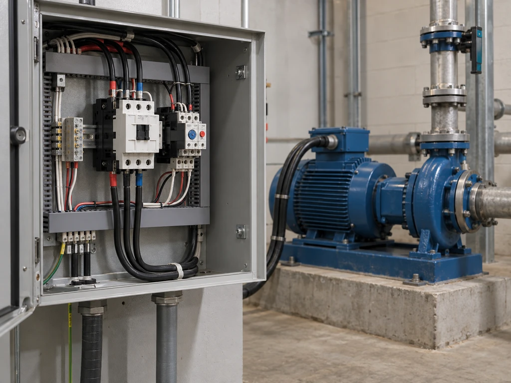
Contactors start and stop pumps, fans, compressors, conveyors, and machine drives. Reversing and star-delta arrangements use multiple contactors with electrical and mechanical interlocking. Motor overload protection normally comes from a separate or integrated overload relay.
Heating Control
Contactors switch resistance-heating banks when the cycling rate is within their electrical-life rating. Frequent temperature-control cycles increase contact wear, so the switching interval and expected number of operations should be checked before choosing mechanical or solid-state control.
Lighting Control
Lighting contactors control groups of luminaires from timers, sensors, building controllers, or remote switches. Drivers, ballasts, and capacitive inputs may create high inrush current, so a resistive-load rating alone is not a reliable basis for selection.
HVAC and Industrial Automation
HVAC systems use contactors for compressors, fans, pumps, and electric heaters. Industrial panels use them for motors and other power circuits controlled by PLC outputs, safety circuits, or process controllers. Auxiliary contacts provide interlocking and operating-state feedback.
For specification support, contact XURUI with the load type, operating voltage and current, utilization category, coil supply, and switching frequency. These details support product selection and quotation.
Frequently Asked Questions
Can a Contactor Stay Energized Continuously?
Yes, if the manufacturer assigns it for continuous duty and the coil receives the correct voltage within the permitted ambient and enclosure conditions. Excess heat, abnormal humming, or discoloration calls for inspection.
What Causes a Contactor Coil to Burn Out?
Excessive voltage, prolonged undervoltage, rapid cycling, high ambient temperature, or an armature that cannot seat fully can overheat the coil. Measure the control voltage during pickup and inspect the core and mechanism before replacing it.
How Do You Know When a Contactor Needs Replacement?
Inspect the contactor if contacts weld, terminals or insulation show heat damage, the mechanism binds, or chatter continues at the correct control voltage. Replace it when these conditions exceed the manufacturer’s maintenance limits.
Can a Contactor Fail in the Closed Position?
Yes. Contacts can weld after excessive inrush, a short-circuit event, inadequate protection, or severe wear. A safety function that requires assured power removal needs suitable system architecture, feedback monitoring, and fault handling rather than one contactor alone.
External Sources
- IEC 60947-4-1:2023 — Electromechanical Contactors and Motor-Starters
- ABB Utilization Categories for Contactors







