

Solid state relays (SSRs) are a quiet, fast, and reliable way to switch high-voltage devices using low-voltage signals. Whether you’re automating a heater, controlling a lamp with an Arduino, or building an industrial panel, this guide will walk you through everything you need to know—clearly and confidently.
What Is a Solid State Relay and How Does It Work?
Solid State Relay vs Mechanical Relay: What’s the Difference?
Mechanical relays work like tiny metal switches. They click open and close when an electromagnetic coil pulls on internal contacts. But over time, the mechanical parts wear out, get noisy, and become less reliable.
Solid state relays, by contrast, have no moving parts. They use semiconductors like triacs or transistors to do the switching. No click, no arc, no bouncing. That means longer lifespan, faster switching, and quieter operation.
Basic Components and Internal Working of an SSR
Inside an SSR, there are two key sides: the input and the output. When a control signal is sent to the input side (typically low-voltage DC), it activates an optocoupler. This safely triggers the switching component on the output side, like a triac or MOSFET.
Because the control and output sides are isolated optically, the low-voltage device (like an Arduino) stays safe even when switching high-voltage loads. That’s one reason SSRs are so popular in sensitive electronic systems.
Common Use Cases for Solid State Relays
You’ll find SSRs in all sorts of places: industrial automation, 3D printers, HVAC systems, home appliances. They’re perfect for switching lights, fans, heaters, and motors. Makers often use them to let microcontrollers safely control high-voltage AC devices.
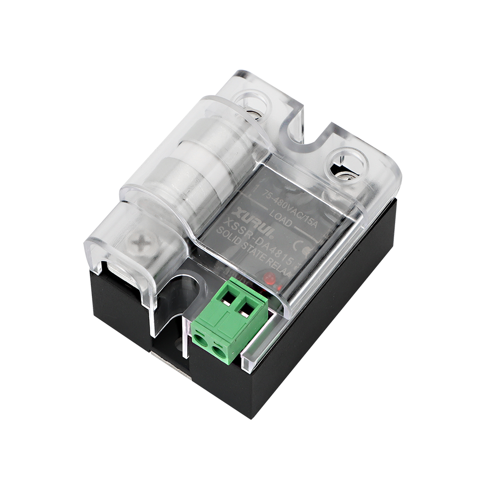
Understanding the Terminals of a Solid State Relay
Now that you understand how SSRs work, let’s get hands-on. Knowing where to connect your wires is essential to avoid confusion and damage.
Input Side (Control Terminals and Trigger Voltage)
The input side—usually labeled “+” and “−” or 3 and 4—receives the control signal. It could be a 5V signal from an Arduino or 24V from a PLC. Always check your relay’s input voltage range. If it doesn’t match, the SSR simply won’t turn on.
Output Side (Load Terminals and Switching Circuit)
The output side—commonly marked 1 and 2—is where the power flows to your load. This is where you switch your AC or DC load on or off. For DC loads, pay attention to polarity. For AC loads, polarity usually isn’t an issue.
Interpreting Terminal Labels and Polarity
Every SSR has labeling, but not every label is the same. Some use numbers, others symbols. The key is knowing which side controls the circuit, and which side carries the load. Read the datasheet if in doubt.
Choosing the Right Type of Solid State Relay
Before you start wiring, you need to make sure you’ve got the right type of SSR for your project. Let’s break it down.
AC-AC, DC-AC, DC-DC – Which One Do You Need?
Match your SSR to the kind of signal you’re using and the load you’re switching. If you’re using a DC control signal to switch an AC load (very common), choose a DC-AC SSR. For DC-to-DC or AC-to-AC needs, pick accordingly.
Selecting the SSR Based on Load Type (Resistive vs Inductive)
Heaters and lamps are resistive loads. Motors and solenoids are inductive. Inductive loads need extra care—like snubber circuits or flyback diodes—to protect the SSR from voltage spikes.
Key Specifications to Consider: Voltage, Current, Trigger Range
Check three key specs: input voltage (can your controller drive it?), output voltage/current (can it handle your load?), and switching type (some SSRs switch at zero-crossing for AC).
Related Reading: Is a solid state relay right for you?
How to Connect a Solid State Relay Step by Step
Got your relay picked out? Great—let’s get it connected. Take your time, double-check everything, and you’ll be fine.
Tools, Power Sources, and Wiring Materials You’ll Need
You’ll need the SSR, a screwdriver, proper-gauge wire, a multimeter, and maybe a heatsink or snubber. Safety gloves are a plus when working with AC circuits.
How to Wire the Control Side Safely (Arduino, PLC, etc.)
Connect your low-voltage control signal to the SSR’s input terminals: digital pin or control output to “+”, ground to “−”. If your controller doesn’t provide enough voltage, use a transistor or driver.
How to Wire the Load Side to an AC or DC Device
Wire the load in series with the SSR’s output. For example: AC live wire to SSR terminal 1, terminal 2 to your lamp, then back to neutral. For DC, connect the correct polarity. Never wire the load across both SSR terminals like a switch.
Final Checks Before Powering the Circuit
Make sure nothing’s loose. Measure voltage across the control terminals. Confirm your load current doesn’t exceed the SSR’s rating. Then power it on and test it.
Example Wiring Diagrams for Common Scenarios
Here are some practical examples to help you see it all in action.
Connecting an SSR to an Arduino and AC Light
Digital pin to SSR +, Arduino GND to SSR −. On the output side, live wire to terminal 1, terminal 2 to light bulb, then to AC neutral. When the Arduino outputs HIGH, the light turns on.
Using a PLC with SSR to Drive a DC Motor
Connect PLC output to SSR input, with proper current/voltage. Output terminals in series with the motor and DC power. Add a flyback diode across the motor to suppress spikes.
Manual Switch and SSR Setup for Controlling a Heater
Wire a manual switch between power and the SSR input. On the load side, wire the heater through the SSR output as you would with a normal switch. Simple, safe, effective.
Tips for Safe and Reliable SSR Operation
A few small things go a long way toward making your SSR setup last longer and work better.
Use Proper Voltage and Current Ratings for Stability
Choose an SSR rated at least 20–30% higher than your expected load. If your heater draws 8A, pick a 10A or 15A SSR. That overhead prevents heat stress and extends lifespan.
Add Heatsinks for Loads Above 5A
SSRs get hot—especially with continuous loads. Mount the relay to a metal panel or use a dedicated heatsink. Follow the datasheet’s thermal recommendations.
Protect Your Circuit with Snubber or Flyback Diode
Snubbers help AC SSRs switch inductive loads without arcing. For DC, flyback diodes across the load prevent voltage spikes from frying the relay.
Test With a Real Load – Not Just a Multimeter
SSRs often need actual current to behave properly. Don’t assume it’s broken if it doesn’t click or light up. Plug in the real thing and observe it under working conditions.
Common Mistakes to Avoid When Connecting an SSR
Let’s save you some frustration by steering clear of these beginner traps.
Confusing Input and Output Terminals
One side is control, the other switches power. Flip them and nothing works—or worse, something burns. Check labels and diagrams.
Using an Undersized Trigger Signal
A 3.3V signal won’t drive a 12V-rated SSR. Either use a logic-level SSR or add a transistor switch between your control and the relay.
Ignoring Heat Dissipation Requirements
No heatsink? Expect failure. Thermal runaway is real. If the relay feels hot to the touch, it needs a cooling solution.
Omitting Circuit Protection (Fuses, Breakers, etc.)
An SSR doesn’t protect your load—you have to. Install a fuse or circuit breaker in line with your high-voltage wiring.
Troubleshooting: Why Isn’t My SSR Working?
SSR giving you trouble? Here’s how to diagnose it.
SSR Not Turning On – Check Trigger Voltage and Polarity
Measure voltage across the control input. If it’s in range but nothing happens, check polarity. DC inputs care which side is + and which is −.
SSR Always On – Understand Leakage and Load Type
Some SSRs leak small current even when off. With low-power loads, this might be enough to keep them dimly lit or spinning. Add a bleeder resistor to drain it off.
Load Flickers or Turns Off Unexpectedly
You might have a poor connection or control voltage drop. Make sure terminals are tight and your controller output is steady.
Relay Overheats or Fails Prematurely
Underrated current, no heatsink, or poor ventilation? Fix those first. Also check for inductive spikes from motors or transformers.
Related Reading: 15 Solid State Relay Troubleshooting Tips to Solve Real Problems
Frequently Asked Questions (FAQs)
Q1: Can I connect a solid state relay directly to an Arduino or Raspberry Pi?
Yes, as long as the SSR accepts 3.3V or 5V input. Otherwise, use a driver transistor or opto-isolated module.
Q2: How do I know if my SSR is AC or DC type?
Look for the label or datasheet symbols. A sine wave indicates AC; a straight line or “+/−” suggests DC.
Q3: Do SSRs require a heatsink?
For anything above 5A, yes. Otherwise, they overheat and fail.
Q4: Why won’t my SSR turn off fully?
Leakage current or inductive loads are common causes. Add a snubber or bleeder resistor.
Q5: Can SSRs switch motors or fans?
Yes—if they’re rated for inductive loads. Be sure to add protection like a flyback diode or snubber.
Conclusion
Solid state relays offer a smart, efficient, and reliable way to control high-voltage circuits using low-voltage logic. By understanding how they work, selecting the right type, and wiring them correctly, you can take full advantage of their speed, silence, and durability. Whether you’re an engineer building automation panels or a hobbyist experimenting with microcontrollers, mastering SSRs opens up a world of safe and powerful switching possibilities. Take your time, follow best practices, and you’ll be switching with confidence in no time.
XURUI Engineering Team






