Industrial SPST toggle switch on a control panel](https://xuruiswitch.com/wp-content/uploads/2026/09/spst-toggle-switch-industrial-control-cover.webp)
An SPST Toggle Switch opens or closes one electrical path with a two-state manual action. In an industrial control panel, the correct part must match the circuit function, electrical duty, installation, environment, and approval scope.
The SPST designation defines only the contact arrangement. The remaining specifications determine whether the switch fits the actual panel and load.
SPST Toggle Switch Selection Steps
Selection should move from circuit logic to verified part-level evidence. The industrial toggle switch collection groups options by circuit form, ratings, terminals, and panel conditions, but the final decision requires the exact model suffix.
Step 1: Confirm the Switching Function and Action
SPST means single pole, single throw: one circuit has one on-off path. It does not provide a second output path, so it fits a simple enable, indicator, or low-voltage control circuit that needs only open and closed states.
SPST toggle switch in a single on-off circuit path](https://xuruiswitch.com/wp-content/uploads/2026/09/spst-switch-on-off-circuit-path.webp)
Define the reference condition before using the word “normal.” For a momentary switch, this is normally the unactuated, spring-return position. A maintained toggle has no inherent at-rest position, so specify the required machine or de-energized condition instead. Where the selected drawing defines a reference condition, record the required contact function as SPST-NO or SPST-NC; SPST alone does not identify a normally open or normally closed function. Then specify whether the action is maintained or momentary and record the exact lever-position sequence, such as ON-OFF, ON-(OFF), or OFF-(ON). The circuit drawing, reference condition, contact function, and operator action must agree before selecting terminals or ratings.
Step 2: Match the Load to the Electrical Rating
Match the exact switch rating to the load voltage type, voltage, current, inrush, load category, and switching frequency. A current value without its associated AC or DC voltage and duty conditions is incomplete selection information.
Do not assume a panel toggle can directly replace a dedicated power-switching device. A motor, solenoid, transformer, or lamp can create inrush or switching stress beyond its steady-state current. Use the switch only where the exact part’s published breaking and carrying ratings cover the intended duty.
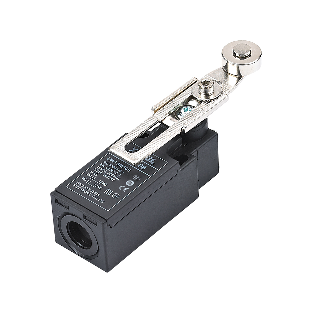
The controlled XURUI industrial switch catalog lists XT rated-load entries of 15 A/250 VAC and 25 A/250 VAC. These entries do not establish the rating of every orderable configuration; confirm the exact model, electrical duty, terminal form, and current controlled document before selection.
Industrial toggle switch beside motor and relay load components](https://xuruiswitch.com/wp-content/uploads/2026/09/industrial-toggle-switch-load-rating-selection.webp)
Step 3: Verify Terminal and Panel Installation Fit
Check the bushing diameter and thread, panel cutout, permitted panel thickness, lever clearance, and rear depth against the actual enclosure drawing. A switch can fit the front hole yet leave inadequate space for insulated terminals or wire bends.
Then match the terminal style to the assembly method. Solder lugs, screw terminals, quick-connect blades, and PCB terminals require different wiring, tooling, service access, and strain-relief arrangements. Verify terminal orientation as well as the number of terminals.
SPST toggle switch panel fit with two rear terminals](https://xuruiswitch.com/wp-content/uploads/2026/09/spst-toggle-switch-panel-fit-terminals.webp)
Step 4: Check Environmental Protection and Service Life
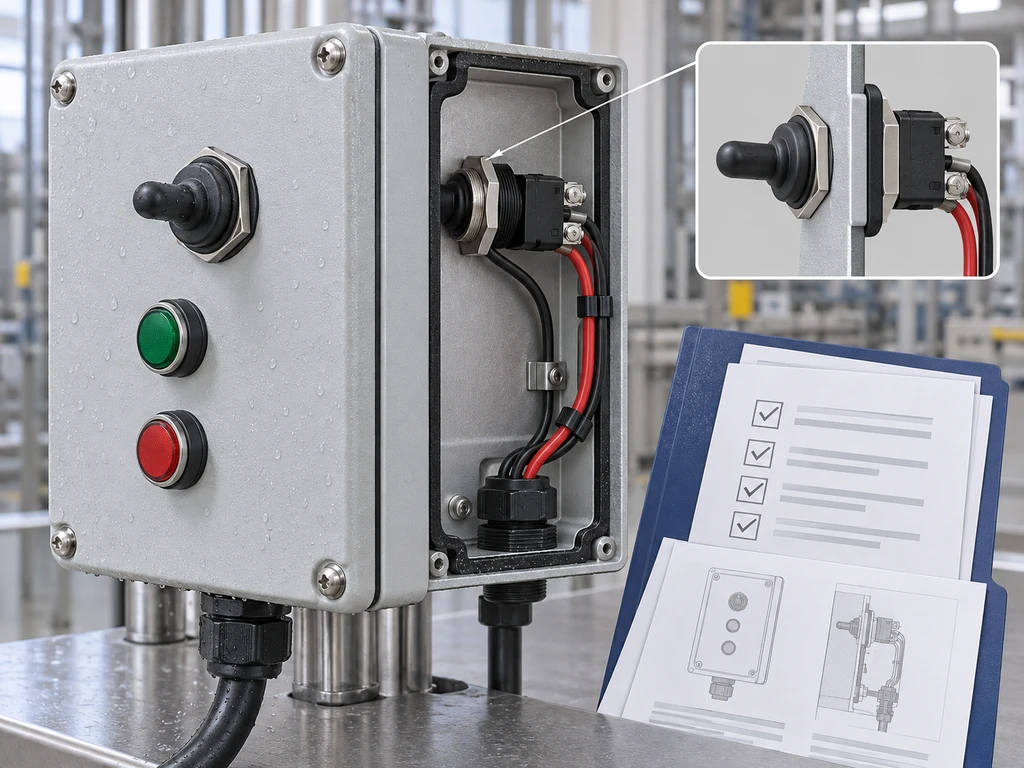
Select ingress protection from the exposure at both sides of the panel. Select protection for the complete installed panel, not only the actuator. A front boot can protect the lever opening only to the rating verified for that exact switch-and-boot configuration; terminals, cable entries, and enclosure joints require separate protection against the stated exposure.
Read mechanical and electrical life separately. Mechanical life is a cycling result without an energized load; electrical life applies a specified load and operating condition. The electrical-life value is the more relevant reference for a loaded control circuit, provided its test conditions match the application.
Step 5: Confirm Approvals for the Exact Part Number
Confirm the certificate, declaration, or recognition record for the complete orderable part number, its electrical rating, and the target market. A family-level approval icon can identify a possible certified configuration, but it does not establish the scope for every terminal, action, seal, or rating variant.
Request the current drawing and approval evidence before design release. If a required approval is not tied to the exact suffix, the compliance conclusion remains open.
Common SPST Toggle Switch Selection Mistakes
These mistakes occur when one visible label is treated as the full specification. A usable selection joins electrical, mechanical, environmental, and compliance evidence.
Specifying Only SPST
SPST defines one switching path, not the contact state, operating action, terminal format, load rating, or installation envelope. Add the defined reference condition, SPST-NO or SPST-NC function where the selected drawing uses those terms, maintained or momentary action, exact lever-position sequence, voltage type, electrical duty, mounting details, and approval requirement to the specification.
For a broader circuit comparison, see SPST, SPDT, and DPDT switching logic.
Using the Switch as a Power Device by Assumption
A toggle switch can control a load only within its published conditions. A switch used to command a contactor or relay coil has a different duty from one used to interrupt a motor or heater directly.
Where the project needs a power-isolation or safety function, select and arrange the switching equipment against that system requirement rather than inferring it from an SPST contact form.
Reading One High Ampere Value as Universal
An ampere value applies only with its stated voltage, current type, load, and test conditions. Do not transfer an AC rating to DC service or treat a rating from one model as applying to every model in the family.
Checking Only Front Sealing
A boot or sealed actuator addresses only part of the installed assembly. The panel’s protection level also depends on the cutout seal, enclosure door, cable entries, rear terminals, and actual exposure direction.
Confusing Mechanical and Electrical Life
Mechanical life indicates endurance without an energized load. Electrical life includes contact stress under a specified load, so it is affected by voltage, current, inrush, switching frequency, and environmental conditions.
Treating a Model-Family Logo as Suffix-Level Approval
A logo on a category or series page is a starting point for verification. Confirm the model designation, ratings, conditions of use, and target-market documentation before placing the part on a released bill of materials.
Get Support from an Industrial Toggle Switch Manufacturer
Contact XURUI engineering and sales with the circuit diagram, defined reference condition, required SPST-NO or SPST-NC function where applicable, maintained or momentary action, lever-position sequence, AC or DC load details, panel cutout, terminal preference, environmental exposure, and target approval. Those details allow the exact configuration and supporting documents to be checked.
FAQs
Can I Use an SPDT Switch as an SPST Switch?
Yes, provided the common terminal and one throw create the required on-off path, and the unused throw is isolated. Verify the printed diagram and continuity in each lever position, because an ON-ON SPDT does not provide a dedicated off position.
Can an AC-Rated SPST Toggle Switch Be Used on DC?
No, unless the exact part also has a published DC rating for the required voltage and load. DC interruption needs separate consideration because current does not naturally cross zero as it does in AC circuits.
How Do I Choose an SPST Toggle Switch for a 12V Load?
Choose a switch with a published 12 VDC-compatible rating that covers the load’s continuous current, inrush, load type, and switching frequency. For motors, solenoids, or other inductive loads, verify the exact DC breaking rating and determine the required suppression method from the load-circuit documentation; running current alone is insufficient.
Does an IP67 Toggle Make the Control Panel IP67?
No. The control panel requires its own installed-assembly protection assessment, including the enclosure, cutout seal, door gasket, cable entries, rear-side exposure, and installation method.
External Sources
- IEC 60529: Degrees of Protection Provided by Enclosures
- Schneider Electric: AC and DC Interruption Differences
- Omron: General Application of Switches
- UL Product iQ Certification Database

SPST toggle switch product on a clean electronics workbench](https://xuruiswitch.com/wp-content/uploads/2026/09/spst-toggle-switch-cover-300x225.webp)