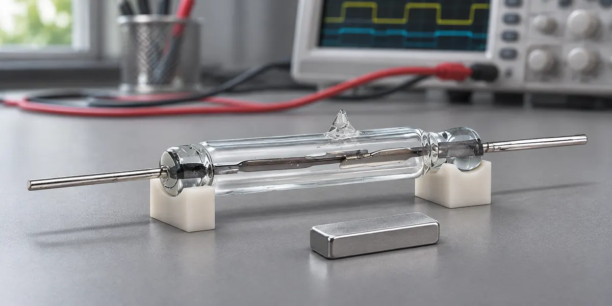
A reed switch’s carry current rating does not tell you how much current it can safely make or break under load. Reed switch current ratings must be read together with the specified voltage, switching power, and load conditions.
This guide explains how to apply those limits and test the selected switch in a working circuit. The numerical examples use DC resistive loads; AC and other loads require their stated ratings.
What Carry Current and Switching Current Ratings Actually Mean
Carry current is the maximum specified current through contacts that have closed and settled. Heating in the conductive path is its main limit. The heat produced follows I²R: current squared multiplied by resistance.
Switching current is the current the contacts can switch under the manufacturer’s stated conditions. It applies during contact opening or closing.
Carry current is often higher, but the two ratings have no fixed conversion. A 1 A carry rating alone cannot establish whether the switch can operate a 1 A load. Electrical capacity is one part of reed switch selection. Contact arrangement, magnetic sensitivity, mounting, and environment also affect the choice.
Why Switching Places More Stress on Reed Contacts
When contacts first close, current flows through a small contact area. A large surge can create enough local heat to weld the surfaces together. The reeds may also bounce, briefly making and breaking the circuit before settling.
As the contacts open, an electrical arc can form across the separating surfaces if circuit conditions sustain it. The arc erodes or transfers contact material. An inductive load can increase this stress by producing a voltage spike when current is interrupted. These brief events explain why contacts can fail even when the load’s running current appears acceptable.
How Voltage and Power Limit the Allowable Switching Current
At a given operating voltage, the current must satisfy both the switching current limit and the switching power limit.
For a DC resistive load:
Current ≤ the lower of maximum switching current and maximum switching power ÷ operating voltage
The voltage must also remain within the switching voltage rating. This calculation screens out unsuitable combinations; it does not establish service life.
The Littelfuse MDSM-10 datasheet, for example, lists 1 A DC carry current, 0.5 A DC switching current, 200 V DC switching voltage, and a 10 W/VA contact rating.
- At 24 V and 0.5 A, the load is 12 W. It exceeds the 10 W limit despite meeting the switching current limit.
- At 12 V and 0.8 A, the load is 9.6 W. It meets the power limit but exceeds the 0.5 A switching limit.
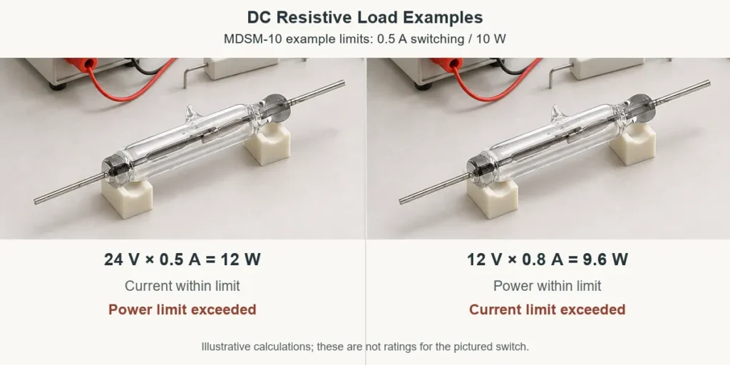
Lower voltage can ease the power constraint, but the maximum switching current still applies. Switching power describes the load being switched, not the heat dissipated in closed contacts.
For the XGH series reed switch, match the exact model code to its current datasheet. Maximum values in a series overview may apply to different models or conditions.
Check the Actual Load Before Direct Switching
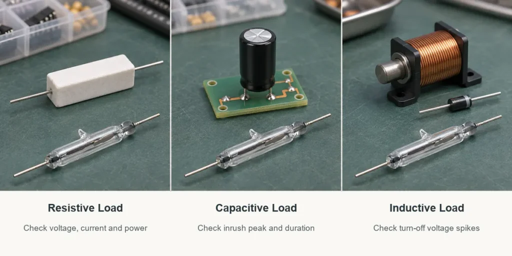
For reed switches connected directly to a load, assess startup and turn-off behavior as well as running current.
Resistive Loads
A stable resistive load provides the simplest case for applying the voltage, current, and power limits. Calculate its current at the highest operating supply voltage. Account for resistance changes during startup. An incandescent lamp draws more current while its filament is cold than after it heats up, so its running current understates the initial load.
Capacitive Loads
A discharged capacitor can draw a sharp current pulse when the contacts close. Circuit resistance and other impedance limit that pulse. Electronic input capacitors and the distributed capacitance of long cables can produce this effect.
Measure the peak current and pulse duration. If they exceed the manufacturer’s permitted switching conditions, add suitable current limiting or use another switching stage. Average current alone will not reveal this risk.
Inductive Loads
Relay coils, solenoids, and motors store magnetic energy. When the contacts interrupt current, that energy can produce a voltage spike and an arc. A correctly connected flyback diode suppresses the spike from a DC coil, though it can slow the load’s release. AC loads need suitable suppression, such as a resistor-capacitor (RC) snubber or a correctly selected voltage clamp.
Suppression reduces contact stress without increasing the published switching current rating. If the load exceeds the contact capability, use the reed as a control input for a suitable power switching device.
Using Carry Current Ratings in Cold-Switching Circuits
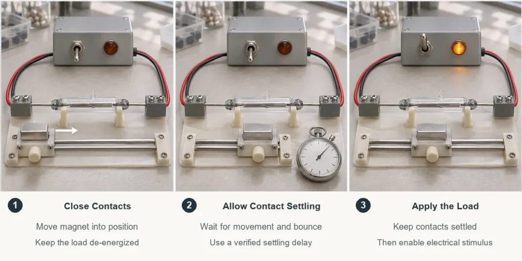
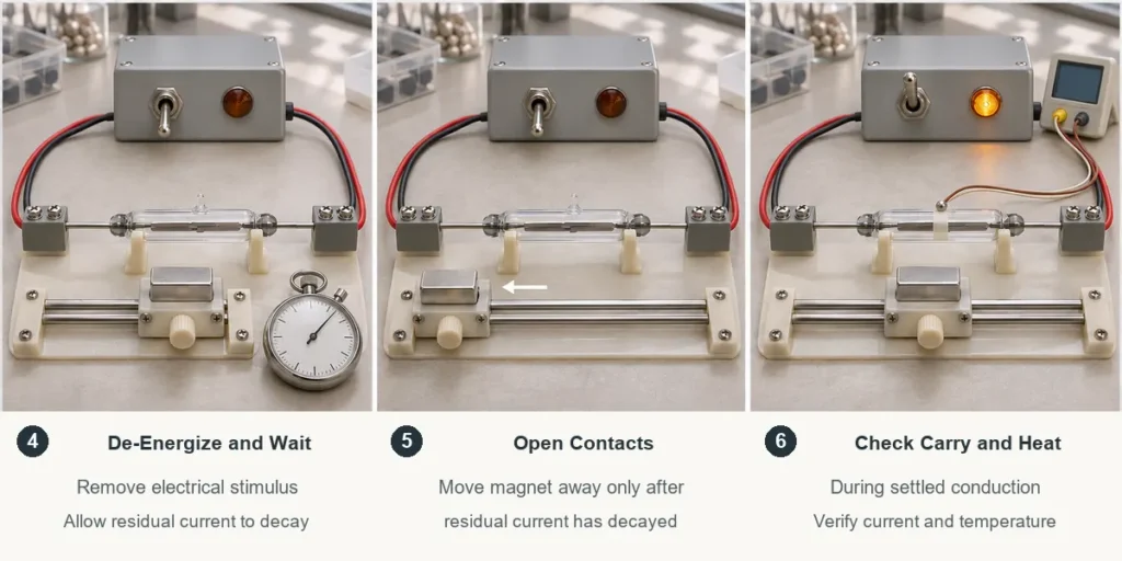
Cold switching allows the contacts to move before the circuit applies or removes the load. Using a higher carry current rating this way requires control over the full opening and closing sequence.
Apply the Load After Contact Settling
Close the contacts and wait for movement and bounce to finish before applying load voltage or current. Set the delay from the specified operating conditions and measured contact behavior. Applying current while the contacts are still bouncing defeats the intended cold-switching sequence.
De-Energize Before Opening
Remove the electrical stimulus and allow residual current to decay before the contacts separate. Turning off a control signal may leave a charged capacitor, an inductive current path, or another supply connected. Confirm that stored energy cannot discharge through the opening contacts. A door or float sensor that opens whenever its magnet moves can rely on cold switching only if the surrounding circuit enforces this timing.
Check Carry Current and Thermal Limits
Keep steady current within the carry rating and evaluate heating in the installed assembly, including enclosure temperature and mounting conditions. A short duty cycle does not automatically permit current pulses above the continuous rating. Use the manufacturer’s pulse limits where provided. Carry current limits apply whenever the contacts conduct, including in circuits that also switch live loads.
Verify Reed Switch Performance in the Actual Circuit
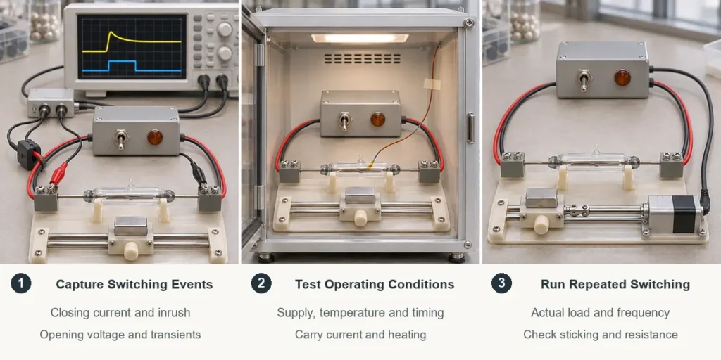
Use an oscilloscope with suitable probes to capture current during contact closure and voltage across the contacts during opening. A multimeter can show running values but may miss short peaks.
Test at the expected supply voltage, temperature, and operating conditions. Confirm that:
- Closing current, including inrush, meets the permitted switching conditions. A pulse carry rating alone does not authorize the same current during closure.
- Opening voltage, including transients, stays within the applicable limits.
- Cold-switching delays prevent contact movement under load.
- Sustained conduction stays within thermal limits.
- Repeated operation produces no sticking, missed releases, or unacceptable contact resistance changes.
An initial test establishes immediate operation. To assess service life, run repeated switching tests at the actual load and frequency, with defined failure criteria.
For model selection, discuss operating conditions with XURUI. Provide the voltage, steady and peak current, load type, switching frequency, ambient temperature, and target operating life so the team can evaluate the electrical requirements.
FAQs
Can Reed Switches Be Connected in Parallel to Handle More Current?
Do not add the live switching current ratings of parallel reed switches. The contacts operate at slightly different times, so one may briefly carry the full switching load. Manufacturer-supported cold-switching arrangements can increase carry capability, provided current sharing and thermal conditions are verified.
Does a Higher AT Rating Mean a Higher Current Rating?
A higher AT rating does not by itself establish a higher contact current rating. AT means ampere-turns and describes magnetic operating sensitivity measured with a test coil. Some electrical ratings also depend on specified sensitivity conditions. The reed switch AT guide explains how this parameter relates to magnetic operation.
Can a Fuse Prevent Reed Switch Contact Welding?
A fuse alone cannot guarantee protection against contact welding. A damaging pulse may occur before the fuse clears. Compare its opening time and the current it lets through with the switch’s withstand capability. Matching ampere labels is insufficient, and the contacts may still need current limiting or suppression.
External Sources
- Littelfuse: MDSM-10 Reed Switch Datasheet
- Pickering Electronics: Understanding Reed Relay Specifications
- Standex Detect: Handling and Load Precautions
- Pickering Electronics: Hot versus Cold Switching
- Pickering Electronics: Dual-Pole Reed Relays
- Littelfuse: Fuseology Design Guide