
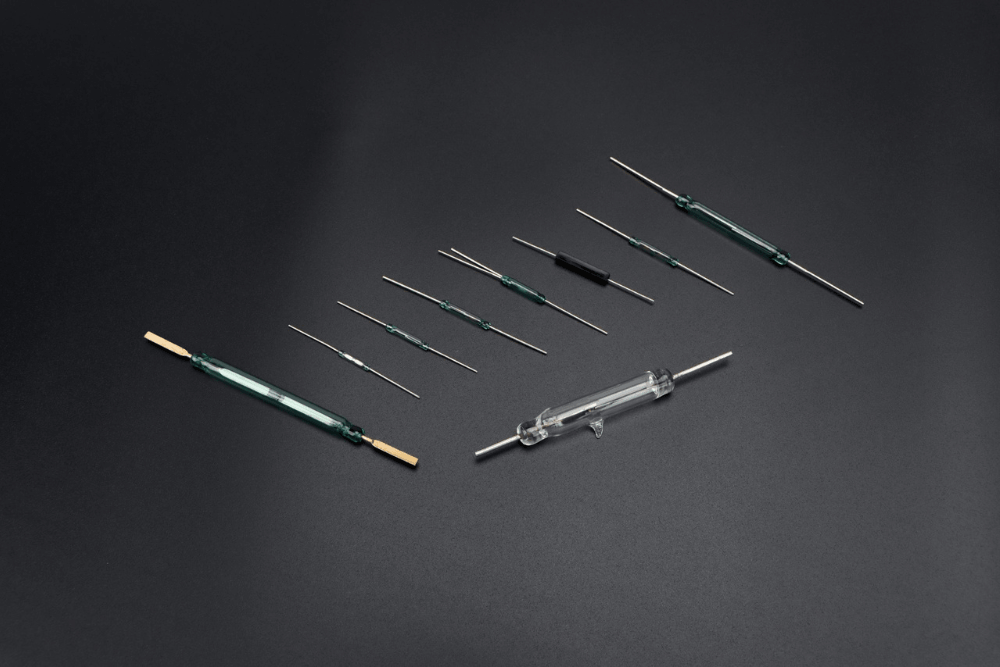
Picking the wrong reed switch is an easy mistake and often a costly one to fix later. A switch that performs well in the lab may fail quickly in real-world conditions. One that meets your voltage needs may still chatter under vibration, while a part that seems compatible may have a contact rating too low for long-term use.
This guide breaks down the five factors that matter most when choosing a reed switch, so you can better evaluate datasheets, find the right replacement, or select the right part for a new design.
Factor 1: Contact Form
The contact form tells you how the switch behaves electrically in its default state, before any magnetic field is applied. This is the starting point for every selection decision because it determines how the switch fits into your circuit logic.
A reed switch in a normally open (Form A) configuration has contacts that are open when no magnet is present and close when a magnet approaches. This is the most common type and works well in applications where you want a circuit to activate in response to a magnetic field, such as triggering a relay, counting rotations, or detecting the presence of an object.
A normally closed (Form B) switch works the opposite way. The contacts are closed at rest and open when a magnet is applied. This type is used when you need a circuit to remain active until a magnetic event occurs, which is common in security sensors and fail-safe systems where a broken connection signals a problem.
A changeover switch (Form C) combines both. It has a common terminal, a normally open contact, and a normally closed contact, giving you the ability to switch between two circuit paths simultaneously. These are more complex and slightly more expensive, but they solve problems that would otherwise require two separate switches.
Getting the contact form wrong means your circuit logic is inverted from the start. It is worth confirming this before anything else.
Factor 2: Switching Capacity
Switching capacity is the combination of voltage, current, and power that the reed switch can safely handle. Every datasheet will list these three values, and all three need to fall within the rated limits at the same time, not just one or two of them.
The voltage rating tells you the maximum voltage that can be applied across the open contacts without causing an arc or breakdown. The current rating tells you how much current can flow through the closed contacts without generating excessive heat or welding the reeds together. The power rating ties both together and often ends up being the actual limiting factor in practice.
A common mistake is selecting a switch that meets the voltage and current requirements individually but exceeds the power rating when those values are combined. For example, a switch rated at 100V and 500mA might have a power rating of 10W. Running it at 100V and 300mA puts you at 30W, which is three times the rated power even though neither the voltage nor current is technically over its individual limit.
Also consider whether your load is resistive or inductive. Motors, solenoids, relays, and transformers are inductive loads that generate voltage spikes when switched off. These spikes can significantly exceed your supply voltage for a brief moment and damage the contacts over time. If you are switching inductive loads, you typically need to add a snubber circuit or use a switch with a higher voltage rating than the supply would suggest.
Related Reading: What Is A Reed Switch And How Does It Work?
Factor 3: Operate and Release Sensitivity
Reed switches do not respond to every magnetic field the same way. The operate point is the magnetic field strength at which the contacts change state, and the release point is the field strength at which they return to their resting state. The difference between these two points is called hysteresis, and it matters a great deal for how reliably your application works.
If a switch has a very low operate point, it will trigger easily in response to weak or distant magnets. This is useful when the magnet cannot be placed close to the switch, but it also makes the switch more susceptible to stray magnetic fields from nearby components, motors, or wiring. In environments with electromagnetic noise, a switch that is too sensitive will generate false triggers.
If the operate point is too high, the magnet needs to be very strong or very close to activate the switch. This is not always practical, especially in applications where the gap between the magnet and switch varies slightly due to mechanical tolerances or movement.
The hysteresis between the operate and release points also affects bounce behavior. A switch with very little hysteresis may chatter at the threshold, switching on and off rapidly as the magnet approaches or recedes. This is rarely acceptable in counting, sensing, or control applications. Selecting a switch with adequate hysteresis for your magnet travel distance reduces the chance of this happening.
When evaluating sensitivity, always consider the magnet you plan to use alongside the switch. The two components need to be matched to each other, not just individually rated for what you need.
Factor 4: Switching Speed and Bounce Time
Reed switches are mechanical devices, and like all mechanical switches they bounce. When the contacts close, they do not simply snap shut and stay closed. They make contact, bounce apart briefly, make contact again, and eventually settle. This process typically lasts between 0.1 and 2 milliseconds depending on the switch design, but those brief bounces can register as multiple switching events in fast digital circuits.
In slow applications like a door sensor or a float switch in a tank, bounce is irrelevant. The system has no reason to react within a millisecond and will simply read a stable state once the contacts settle. But in pulse counting, encoder feedback, or any application where the controller is watching for edges or transitions, bounce can produce incorrect counts or erratic behavior.
If your application is sensitive to bounce, you have two options. The first is to use debounce logic in firmware or hardware, which ignores transitions for a short window after the first detection. The second is to select a switch with a shorter bounce time, which some manufacturers specify in their datasheets.
Switching speed is a separate consideration from bounce. It refers to how quickly the switch can cycle between open and closed states in continuous operation. High-speed applications like reed switch-based pulse generators or proximity sensors in rotating machinery need switches rated for frequent cycling at the required frequency. Exceeding the rated switching speed can cause contact wear far faster than expected.
Factor 5: Environmental Conditions
A reed switch that performs well in a controlled environment can degrade quickly when exposed to the conditions of real-world use. Temperature, humidity, vibration, and the presence of corrosive gases or chemicals all affect how long a switch lasts and how reliably it performs.
Temperature range
Most standard reed switches operate reliably between about minus 40 and plus 125 degrees Celsius, but this varies by manufacturer and design. Applications in automotive engine compartments, industrial furnaces, outdoor equipment in extreme climates, or refrigeration systems all push temperature limits. Always verify that the switch you select is rated for the full range your application might see, not just the average operating temperature.
Humidity and sealing
The glass envelope of a reed switch provides basic protection, but the lead wires where they exit the glass are potential entry points for moisture if the switch is not properly sealed or potted. In high-humidity environments, condensation on or near the contacts can cause corrosion or electrical leakage over time. For outdoor, marine, or washdown applications, look for switches that are specifically rated for moisture resistance or that are designed to be potted in epoxy during assembly.
Vibration and shock
The reeds inside a reed switch are thin and springy by design, which means they respond to vibration just as they respond to magnetic fields. In high-vibration environments like vehicles, machinery, or industrial equipment, a reed switch mounted without proper isolation may chatter or produce intermittent signals even when no magnet is present. Some reed switches are manufactured with stiffer reeds or special designs that are more resistant to vibration-induced false switching, and these should be specified for any application where vibration is a concern.
Atmosphere and gases
Reed switches are hermetically sealed, which normally protects the contacts from atmospheric contamination. However, certain gases can permeate through glass over time at high temperatures, and hydrogen in particular is known to cause issues with gold-plated contacts in some switch designs. If your application involves elevated temperatures in the presence of specific gases, this is worth checking with the manufacturer before committing to a particular switch design.
A Few More Things Worth Checking Before You Finalize Your Selection
Once you have worked through the five main factors, there are a handful of additional details that can save you from problems later.
Contact material matters more than most people expect. Rhodium-plated contacts offer excellent wear resistance and are a good general choice. Gold-plated contacts provide lower contact resistance and better performance at very low currents, making them a better fit for signal-level switching where reliable continuity is more important than high current handling. Tungsten contacts are used in higher power applications where the contacts need to withstand the energy of frequent arcing.
The physical size and package format of the switch needs to match your board layout or mechanical assembly. Reed switches come in a wide range of lengths and diameters, and the lead spacing varies between products. If you are replacing a switch in an existing design, measure the original before ordering a replacement, as the same nominal specification can come in different physical formats from different manufacturers.
Cycle life is worth looking at if your application involves frequent switching. A reed switch in a flow meter that counts thousands of pulses per day has very different lifetime requirements than a switch in a lid sensor that opens and closes a few times a day. Manufacturers typically rate cycle life in millions of operations, and the actual lifetime depends heavily on the load being switched. Lower loads generally produce much longer cycle life than switching at or near the rated maximum.
Final Thoughts
Reed switches are simple components, but that simplicity can make it tempting to treat them as interchangeable commodity parts. In practice, the differences between switch types, sensitivity levels, contact materials, and environmental ratings have a real impact on whether a design works reliably over its intended lifetime or starts generating problems after a few months in the field.
Working through the five factors in this guide before finalizing a selection takes a little extra time upfront but saves a significant amount of rework, warranty returns, and field failures down the line. When in doubt, test with the actual magnet and load you plan to use, and consult the manufacturer if your application pushes toward any of the limits on the datasheet.
XURUI Engineering Team







