
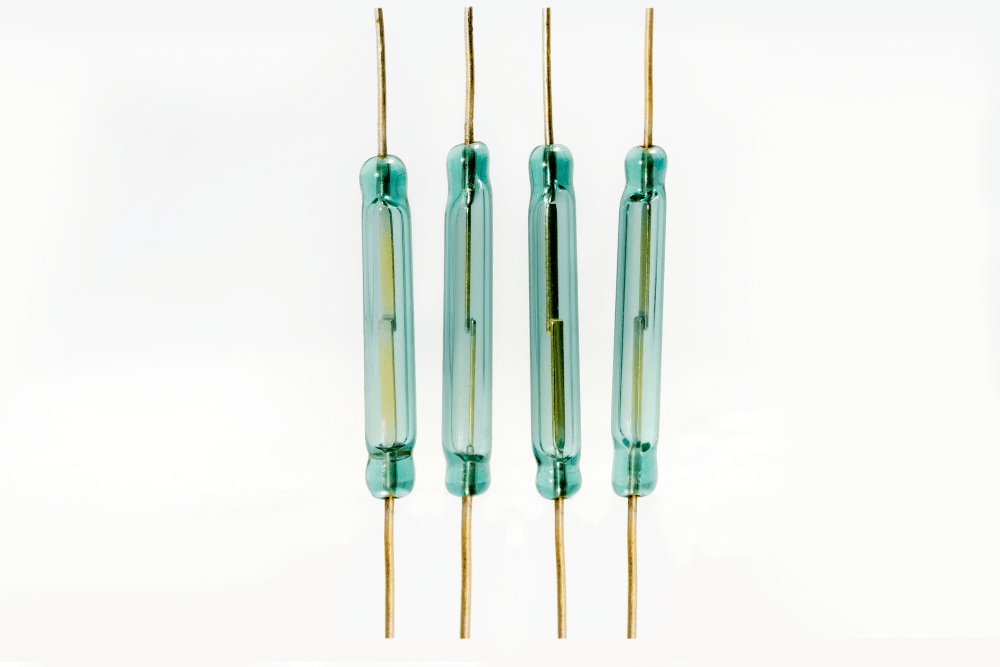
You replace a reed switch, everything works fine for a while, and then the same problem comes back. The switch stops responding, the contacts weld together, or the readings become erratic. It feels like the component is just bad, but in most cases the switch itself is not the real problem. Something in the application is stressing it beyond what it was designed to handle.
Reed switch failures almost always have a root cause. Once you know what to look for, most of them are fixable without changing the fundamental design. This guide walks through the most common reasons reed switches fail prematurely and what you can do about each one.
You Are Exceeding the Switching Capacity
This is the most common cause of early reed switch failure, and it often goes undetected because the switch appears to work at first. The contacts handle the load fine in the short term but degrade faster than they should, eventually failing after a few thousand cycles instead of the millions the datasheet promises.
Every reed switch has three rated limits: maximum voltage, maximum current, and maximum switching power. All three apply simultaneously. A switch rated at 100V and 1A might have a power rating of only 10W. If you run it at 80V and 500mA, you are at 40W, which is four times the rated power limit even though neither the voltage nor the current individually looks out of range.
Exceeding these limits causes arcing between the contacts every time the switch opens or closes. Over time, arcing deposits carbon on the contact surfaces, erodes the contact material, and eventually either welds the contacts shut or pits them badly enough that they can no longer make reliable contact.
The fix is to check your actual load against all three ratings, not just the ones that seem most relevant. If your load is at or near the limits, step up to a switch with higher ratings or add an intermediate relay so the reed switch only handles the coil current rather than the full load.
You Are Switching an Inductive Load Without Protection
Resistive loads like simple resistors or incandescent bulbs are relatively gentle on reed switch contacts. Inductive loads are not. Motors, relays, solenoids, and transformers store energy in their magnetic field, and when the switch opens and interrupts the current, that stored energy has to go somewhere. It appears as a voltage spike across the contacts that can be many times higher than the supply voltage, lasting only microseconds but more than enough to cause arcing damage with every switching event.
If you are switching an inductive load and your reed switches keep failing, this is almost certainly why. The contacts are being hit with voltage spikes far above what the switch is rated for, and each spike deposits a tiny amount of damage that accumulates over time.
The solution is to add a snubber circuit or a flyback diode across the inductive load to absorb those spikes before they reach the switch contacts. For DC circuits, a simple diode placed across the coil in reverse polarity is usually sufficient. For AC circuits, an RC snubber network works better. This is a standard practice when switching inductive loads and makes a significant difference in contact life.
The Switch Is Being Operated Too Frequently
Reed switches have a rated cycle life, typically expressed in millions of operations. That number assumes the switch is being operated at a reasonable rate with the rated load. High-frequency switching compresses all those cycles into a much shorter period of real time, and it also gives the contacts less time to cool between operations, which accelerates wear.
In applications like flow meters, encoders, or proximity counters on fast-moving machinery, a reed switch might cycle hundreds or thousands of times per minute. A switch rated for 100 million cycles sounds like a lot, but at 1,000 cycles per minute that works out to roughly 69 days of continuous operation before the rated life is exhausted. In practice, the switch may fail sooner if the load is not kept well below the rated maximum.
If your application involves high switching frequency, look specifically for switches rated for that use case. Some manufacturers offer reed switches designed for high-speed applications with stiffer reeds and contact materials that tolerate frequent cycling better. Alternatively, consider whether a solid-state sensor such as a Hall effect sensor would be a better fit for high-cycle applications, since it has no contacts to wear out.
Related Reading: How Long Does a Reed Switch Last?
The Magnet Geometry Is Wrong
A reed switch operates most reliably when the magnet approaches and recedes cleanly along the switch axis. Problems arise when the magnet moves in a direction or at an angle that causes the reeds to partially actuate, hover near the operate threshold, or transition through the operate and release points very slowly.
Slow or partial actuation is bad for two reasons. First, contacts that close slowly are more likely to bounce, generating multiple false switching events. Second, contacts that linger near the threshold are partially in contact, which concentrates the switching energy into a very small contact area and accelerates wear at that spot.
The operating gap between the magnet and switch also matters. If the magnet is mounted too far away and only barely activates the switch, small changes in alignment due to vibration or mechanical wear over time can cause intermittent operation. If the magnet is too close and the field is too strong, the contacts may struggle to release properly.
When troubleshooting geometry-related failures, check that the magnet approaches the switch along a predictable path, that the gap is within the manufacturer’s recommended range, and that there is no lateral offset between the magnet and switch centerlines that would cause uneven reed actuation.
Vibration Is Causing False Switching or Fatigue
The metal reeds inside a reed switch are thin and springy, which is exactly what makes them responsive to magnetic fields. It also means they respond to mechanical vibration. In high-vibration environments such as vehicles, industrial equipment, HVAC systems, or anything with rotating machinery nearby, the reeds can vibrate at certain frequencies and momentarily make or break contact even when no magnet is involved.
Vibration-induced false switching is annoying in control systems and dangerous in safety-critical applications. But the bigger long-term risk is fatigue. Reeds that are vibrating continuously experience repeated micro-flexing of the metal, and over time this can cause cracks to form at the base of the reed, eventually leading to fracture and complete switch failure.
If vibration is a factor in your environment, mount the switch so that its axis is aligned with the primary direction of vibration rather than perpendicular to it, as this reduces the bending stress on the reeds. Use vibration-damping mounts where possible. Some manufacturers produce switches specifically designed for high-vibration environments with stiffer reeds or encapsulated designs that reduce the amplitude of reed movement.
Temperature Is Outside the Rated Range
Most reed switches have a rated operating temperature range, and exceeding it in either direction causes problems. At high temperatures, the glass envelope of the switch can soften slightly, the hermetic seal can degrade, and the spring properties of the reed metal change in ways that shift the operate and release sensitivity. Contacts that were properly calibrated at room temperature may not behave the same way at elevated temperatures.
At very low temperatures, the reeds become stiffer and may require a stronger magnetic field to actuate than at room temperature. If your magnet and switch combination was tuned for room temperature operation, it may become unreliable in cold environments.
Applications in engine compartments, outdoor enclosures in extreme climates, industrial ovens, refrigeration equipment, or anywhere near high-power electronics that generate substantial heat all need switches specified for that temperature range. Check the datasheet minimum and maximum temperature ratings, and verify that the worst-case temperature your installation will see is within those limits with some margin to spare.
Moisture or Contamination Has Reached the Contacts
Reed switches are hermetically sealed, but the seal is at the glass-to-metal junction where the lead wires exit the switch body. In harsh environments, this junction can be a point of vulnerability, especially if the switch has been mechanically stressed or if the leads have been repeatedly bent near the glass.
Once moisture gets inside the glass envelope, it can cause corrosion on the contact surfaces, increase contact resistance, and make the switch unreliable or non-functional. In some cases the contacts corrode so badly that the switch appears to be permanently open even when actuated with a strong magnet.
For applications in humid, wet, outdoor, or washdown environments, select switches that are rated for those conditions or plan to pot the switch in epoxy as part of your assembly process. Potting encapsulates the entire switch including the lead exits and provides excellent protection against moisture ingress. Avoid bending the leads close to the glass body, as this can crack the seal even if the bend looks minor.
The Switch Was Damaged During Assembly
Reed switches are more fragile than they look. The glass envelope can crack from mechanical stress, and a cracked envelope destroys the hermetic seal and exposes the contacts to the atmosphere. Even a hairline crack that is not visible to the naked eye is enough to cause long-term reliability problems.
Common assembly mistakes that damage reed switches include bending the leads too close to the glass body, applying too much heat during soldering, clamping the switch too tightly in a fixture, dropping it onto a hard surface, and pressing on the glass body when inserting it into a PCB or housing.
When handling reed switches, always grip the leads rather than the glass body. When bending leads, hold the lead between the bend point and the glass with pliers to absorb stress before it reaches the glass. When soldering, work quickly or use a heat sink clip on the lead between the solder joint and the glass to prevent heat from conducting up into the seal. If your assembly process involves any step that puts mechanical stress on the glass, consider whether a protective sleeve or potting material should be applied before that step.
How to Diagnose Which Failure Mode You Are Dealing With
When a reed switch fails, the way it fails usually points to the root cause. A switch with welded contacts that stays permanently closed almost always indicates overcurrent or excessive power switching, often combined with an inductive load. A switch with pitted, corroded, or high-resistance contacts that no longer closes reliably suggests arcing damage from voltage spikes or moisture contamination. A switch that produces intermittent signals despite correct magnetic alignment points to vibration-induced switching or a cracked seal. A switch that works fine in testing but fails quickly in the field often means the operating environment is harsher than expected in terms of temperature, vibration, or load.
Examining failed switches under magnification when possible gives you direct evidence. Contact surfaces that look rough, blackened, or melted point to electrical overload. A cracked glass envelope points to mechanical damage. Corrosion on the leads or contacts points to moisture. Comparing the appearance of a failed switch to a new one makes it much easier to identify what went wrong.
Final Thoughts
Reed switches fail for predictable reasons. Overloaded contacts, inductive voltage spikes, excessive cycling frequency, poor magnet geometry, vibration, temperature extremes, moisture ingress, and assembly damage are the causes that account for the vast majority of premature failures in real applications.
The good news is that every one of these is avoidable. Selecting the right switch for the actual load and environment, protecting inductive loads with suppression components, managing magnet alignment carefully, and handling the switch properly during assembly will get you the reliable long-term performance that these components are fully capable of delivering.
XURUI Engineering Team







