
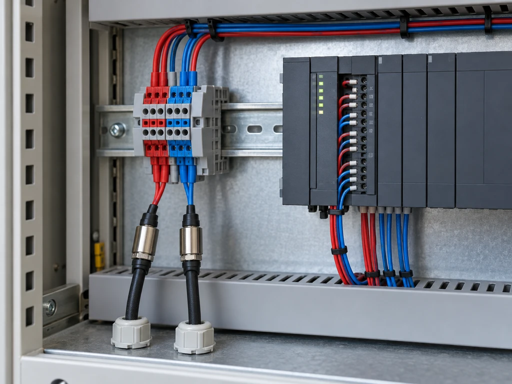
Sinking and sourcing describe how current moves through a DC input circuit. In sourcing vs sinking wiring, a PNP sensor sources current to a sinking PLC input, while an NPN sensor sinks current from a sourcing PLC input.
Correct wiring depends on the sensor output, PLC input circuit, supply polarity, and complete current path. The same principles apply to dry-contact switches.
What Do Sinking And Sourcing Mean?
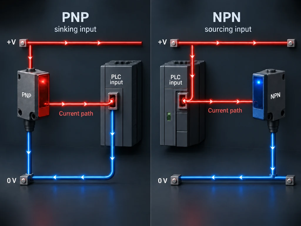
A sourcing device supplies conventional current from the positive DC rail. A sinking device provides the return path to 0 V. A conventional 24 VDC input loop needs one sourcing side and one sinking side.
The terms apply to both sides of the circuit. A PNP output sources current, while an NPN output sinks it. On the PLC side, a sinking input receives current and returns it to 0 V; a sourcing input supplies current for the field device to switch to 0 V.
Sinking and sourcing describe current direction and common polarity. They are separate from normally open (NO) and normally closed (NC) operation. Devices in this limit switch collection use dry contacts, so the external wiring determines the input circuit type.
How Do PNP And NPN Sensors Match PLC Inputs?
PNP sensors match sinking PLC inputs, while NPN sensors match sourcing PLC inputs. The sensor output rating, PLC input voltage, ON current, OFF leakage current, and supply reference must also satisfy both datasheets.
| Sensor Output | Compatible PLC Input | Common Connection | Active Output |
| PNP, sourcing | Sinking | PLC input common to 0 V | Output switches toward +V |
| NPN, sinking | Sourcing | PLC input common to +V | Output switches toward 0 V |
PNP Sensor With A Sinking PLC Input
A PNP sensor switches +V to a sinking PLC input. Connect the PLC input common to 0 V and the sensor output to the input terminal.
Current path: +V → PNP output → PLC input → 0 V common.
The active output may remain below the supply voltage because of internal voltage drop. It must still exceed the module’s ON-voltage and ON-current thresholds.
NPN Sensor With A Sourcing PLC Input
An NPN sensor switches the signal toward 0 V for a sourcing PLC input. Connect the PLC input common to +V and the sensor output to the input terminal.
Current path: +V common → PLC input → NPN output → 0 V.
Moving the signal wire cannot make an NPN output compatible with a fixed sinking input. The module must support the required common polarity and input circuit.
How Do You Wire Devices To A PLC Input?
Wire the device so its active state completes the specified current path. De-energize and secure the circuit before changing conductors, then follow the terminal diagram for the exact device and input module.
Three-Wire Sensor Wiring
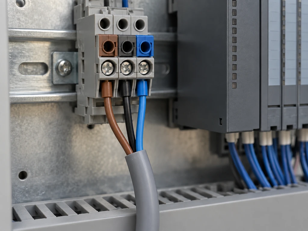
Many three-wire DC sensors use brown for +V, blue for 0 V, and black for the switched output. The device diagram takes precedence. Connect brown and blue to the rated supply, black to the PLC input, and the PLC common to 0 V for a sinking input or +V for a sourcing input.
If the sensor and PLC use separate supplies, connect their reference points as the manufacturers require unless the interface is isolated. Check the output-current limit, residual voltage, and leakage current.
Dry-Contact Switch Wiring
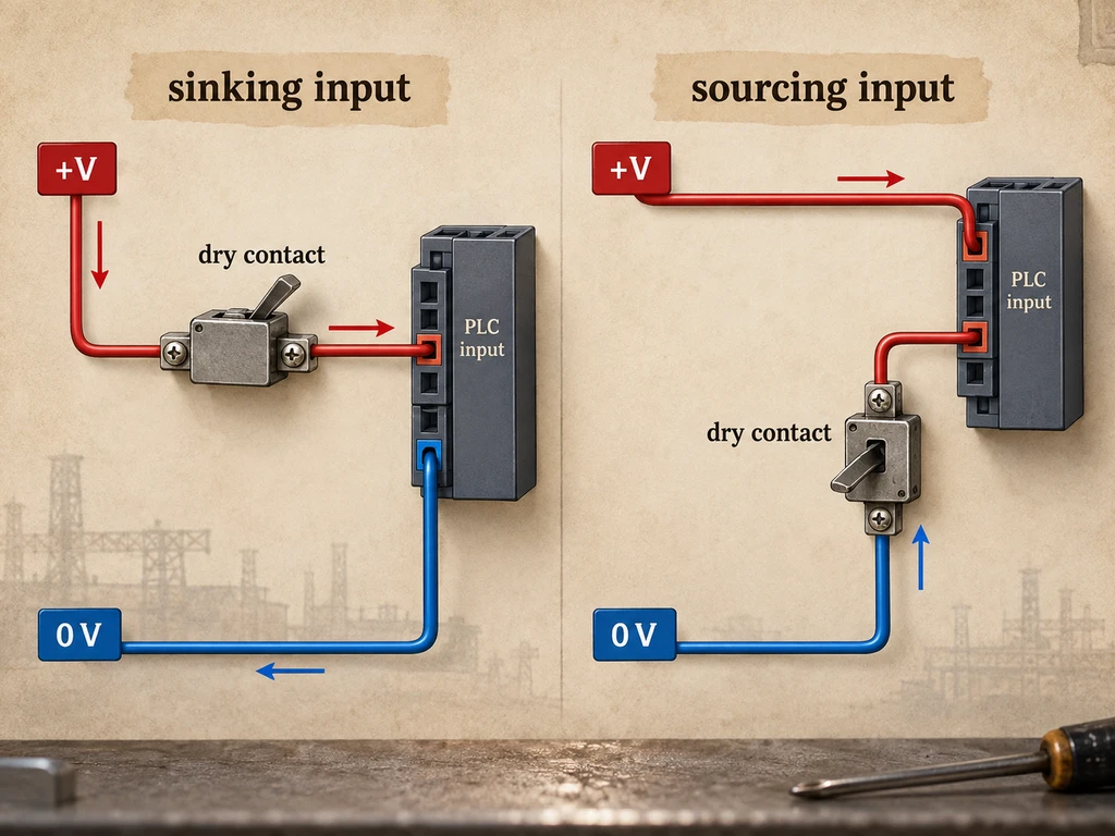
A dry contact has no inherent PNP or NPN polarity. For a sinking input, connect +V through the contact to the input and connect the input common to 0 V. For a sourcing input, connect the common to +V and place the contact between the input and 0 V. For position or limit-control applications, the XZ-15 series micro switch may be a suitable dry-contact option. Confirm the contact logic, terminal arrangement, and DC rating of the exact model before use.
How Can You Identify The PLC Input Type?
Identify the input type from the module diagram and common-terminal polarity. If the documentation is unclear, verify the current path under controlled test conditions. A “24 VDC input” label alone does not identify the circuit type.
Module Diagram And Common Polarity
Find the input group’s COM, M, L+, S/S, or equivalent terminal in the hardware manual. A common connected to 0 V normally indicates a sinking input for PNP signals. A common connected to +V normally indicates a sourcing input for NPN signals.
Some modules support either polarity through a configurable common; others are fixed. Check each group because one module may divide its channels among several commons. Match all front-label symbols to the exact catalog number and hardware revision.
Input Voltage And Current-Path Verification
Under an approved live-testing procedure, measure the signal terminal relative to 0 V in both device states. An active PNP signal should move toward +V. An active NPN signal should move toward 0 V. Compare both readings with the module’s ON and OFF thresholds. Voltage alone is insufficient if the circuit cannot supply the required input current. If the reading floats or changes under load, trace the full loop.
How Do You Verify The Wiring?
Check the supply and common first, then test the field output and PLC input separately. A sensor LED or PLC input LED shows state, but it cannot confirm the entire electrical and software path.
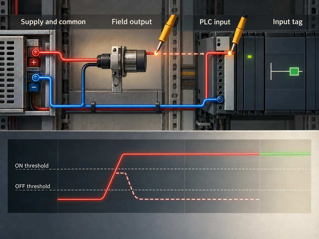
Power And Common Check
Measure the DC supply at the sensor and PLC terminals. Check polarity, rated voltage range, fuses, and continuity of the required common. A correct supply reading does not confirm that the input group common is connected. Use continuity or resistance mode only on isolated, de-energized conductors.
Sensor Output And PLC Input Check
Operate the sensor while measuring its output at the PLC terminal. The signal must cross the module’s state threshold and remain stable long enough for the input filter and PLC scan to detect it. Compare the terminal voltage, module LED, input tag, and program logic in that order.
For mechanical contacts, the limit switch testing guide adds de-energized continuity testing and actuator inspection. A passing continuity test confirms contact switching, but not the powered PLC current path.
How Do You Troubleshoot A PLC Input?
Find the first point where the expected current path or logic state disappears. Measure against the correct reference and compare the result with the exact module and sensor specifications.
| Input Symptom | Possible Cause | Verification Step | Corrective Direction |
| Input never turns ON | PNP/NPN mismatch or open loop | Trace common polarity and active current path | Use a compatible input, sensor, or interface |
| Input always ON | Wrong common, short, or excessive leakage | Disconnect field output and measure input state | Correct wiring; evaluate an approved bleeder or interface |
| Input changes at sensor only | Broken signal wire or wrong terminal | Measure output at sensor and PLC terminals | Repair the conductor or use the assigned input |
| Input flickers | Noise, loose connection, marginal voltage, or bounce | Trend terminal voltage and inspect terminations | Correct wiring, separation, shielding, or filtering |
PNP/NPN And PLC Input Mismatch
If the device LED changes but the PLC input does not, check whether the active output rises toward +V or falls toward 0 V. Compare that behavior with the module common. Use a compatible channel, configurable common, approved signal conditioner, or interposing relay to correct a mismatch.
Common And Power-Supply Faults
A missing group common opens the loop even when the sensor and PLC have power. Check the loaded voltage, fuses, disconnects, shared-reference requirements, and conductor voltage drop. If the supply voltage collapses, locate the overload or short circuit before replacing the sensor.
Leakage Current And Unstable Signals
OFF-state leakage can keep a PLC input falsely active. Compare the sensor’s leakage current and residual voltage with the input’s OFF-current, OFF-voltage, and impedance limits. Use only a manufacturer-approved bleeder resistor or isolated interface, and calculate resistor power dissipation from the actual supply voltage.
For a flickering input, separate signal and power wiring, tighten the terminals, and compare the signal duration with the input filter and PLC scan. Correct the electrical fault before increasing software debounce.
For application review, send XURUI the sensor output type, PLC input module number, supply voltage, and required contact logic through XURUI’s contact channel. This information helps verify the circuit and switch configuration before quotation.
FAQs
Does PNP Or NPN Affect Normally Open And Normally Closed Operation?
No. PNP or NPN defines the transistor output’s current direction. NO or NC defines whether the output is active in the device’s normal condition. A sensor may be PNP-NO, PNP-NC, NPN-NO, or NPN-NC if the manufacturer offers that configuration.
Can PNP And NPN Sensors Be Used In The Same PLC System?
Yes, if separate input groups support the required common polarities or suitable interfaces isolate the signals. Do not place both types on one fixed-polarity common unless the module manual permits it.
Can An Interface Relay Convert A PNP Signal To An NPN Signal?
Yes. The sensor can energize a compatible relay coil, and the isolated dry contact can be wired for the PLC input’s required polarity. Check the coil voltage and current, sensor output capacity, response time, and DC suppression polarity.
Are PNP Sensors More Common Than NPN Sensors?
Neither type is universally more common. Usage varies by region, equipment sector, and installed system. Select the output type from the PLC input specification rather than an assumed convention.
Does The Choice Between PNP And NPN Affect PLC Programming?
It can change how the physical signal maps to an ON or OFF input state, but the transistor type does not determine the control logic. Program for the required machine condition, then account for NO/NC behavior or input inversion where needed.
External Sources
- Siemens: Connection of Sensor Types According to IEC 61131-2 to Digital Input Modules
- Banner Engineering: PNP vs NPN—What Makes These Outputs Different?
- OMRON CP1E CPU Unit Hardware User’s Manual







