
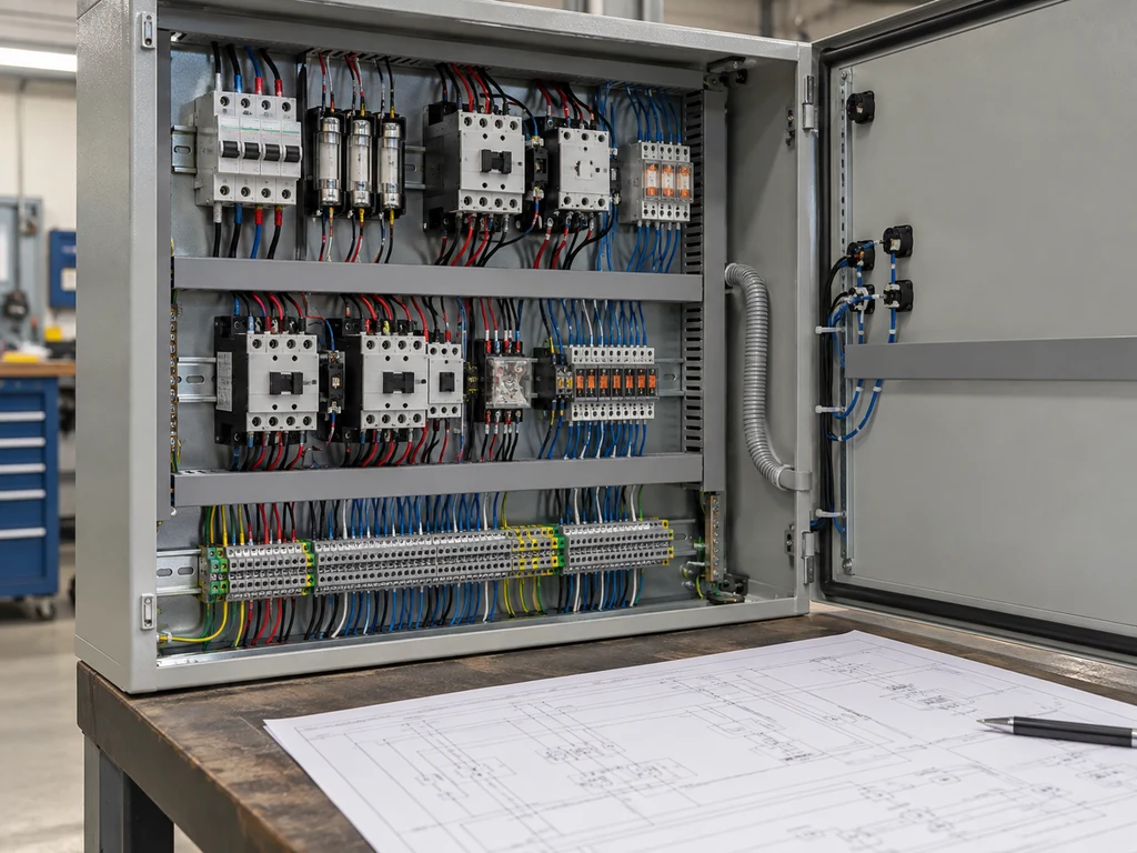
An electrical panel wiring diagram shows how power, control signals, protective devices, and field connections link within and beyond a panel. Read it by checking the drawing references and power sources first, then tracing each circuit through its devices to the load and its return or reference conductor.
This guide focuses on industrial control panels. It explains the labels used on a drawing, a five-step tracing method, and a direct-on-line motor starter example that shows how the power and control paths work together.
What Is an Electrical Panel Wiring Diagram?
An electrical panel wiring diagram identifies the conductors, terminals, devices, and connections used to build or troubleshoot a panel circuit. In an industrial control system, it connects the design intent to physical parts such as breakers, fuses, switches, relays, contactors, terminal blocks, sensors, and loads. A range of industrial control components may appear across several sheets, so read the diagram as part of a connected drawing set because one sheet rarely contains the entire circuit.
A wiring diagram typically emphasizes physical connections and termination points. A schematic usually emphasizes circuit function and logic, while a panel layout shows where devices are mounted. The exact level of detail depends on the project drawing standard. These documents may reference one another, but each serves a different purpose. Use the wiring diagram to determine where a conductor terminates, and use the schematic to understand how the circuit operates.
How to Read Electrical Panel Diagram Labels?
Begin with the document controls and legend before following any line. They define the symbols, references, and electrical values used throughout the drawing set.
Drawing Information and Legend
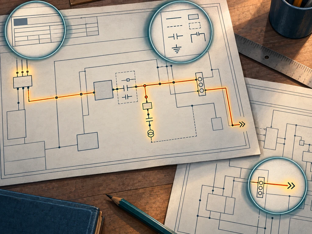
Read the title block for the equipment name, drawing number, sheet number, revision, and applicable drawing standard. Check that the panel identification and revision match the equipment in front of you. The legend defines symbols, abbreviations, line styles, and reference conventions. If a tag differs from a common industry convention, follow the project legend.
Power Supply and Voltage
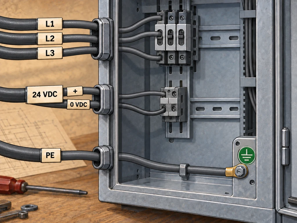
Identify every source shown on the drawing, including sources other than the main incoming supply. A panel may contain line voltage, a control transformer secondary, a 24 VDC power supply, an external field supply, or a separately supplied circuit. Mark L1, L2, L3, neutral, DC positive, and 0 VDC according to the drawing. Protective earth provides bonding and fault protection; it is not a normal load-current return.
Component and Connection Labels
Separate the labels by function. A device tag identifies a component, a wire number identifies a conductor or connection reference, and a terminal number identifies a physical connection point. The exact meaning depends on the project drawing convention.Common tags include Q for a breaker, F for a fuse, K for a relay or contactor, S for a switch, M for a motor, and X for a terminal block. These conventions vary by project and manufacturer.
With the XT Series toggle switch, the contact configuration and terminal format determine how the device is shown and connected in a panel drawing. Before wiring, compare the diagram with the switch’s physical terminal markings and product documentation.
How to Follow an Electrical Panel Wiring Diagram Step by Step?
Follow the circuit in functional order. Establish the document context, identify the sources, trace the power, trace the control logic, and resolve each reference until the circuit is complete. Page layout can vary, so follow the electrical relationship instead of relying on line direction.
Step 1: Review the Drawing Information
Confirm the title block, equipment tag, revision, sheet number, legend, and drawing standard. Before touching conductors during service work, follow the site energy-control procedure. Isolate every hazardous energy source, make stored energy safe, and verify the deenergized condition through the required qualified-person procedure.
Step 2: Identify the Power Sources and Circuit Types
List each source and mark the circuit it feeds. Separate the main power circuit from the control, safety, PLC I/O, and signal circuits. This prevents a low-voltage control connection from being mistaken for a motor supply or a safety interlock from being treated as an ordinary start command.
Step 3: Trace the Main Power Circuit
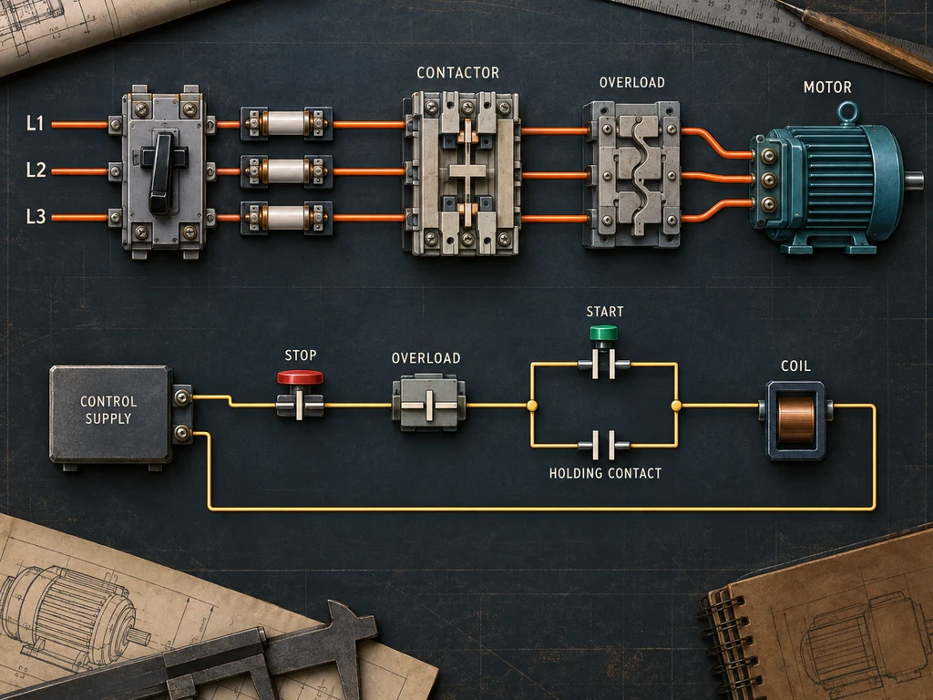
Start at the identified source and follow each conductor through its protective and switching devices to the load. A typical direct-on-line motor path may be:
L1/L2/L3 → disconnect or breaker → fuses → contactor → overload relay → motor
Use the drawing legend for the actual device designations. A three-phase motor circuit usually follows phase-to-phase paths and does not require a neutral return. Track the protective earth connection separately as a bonding and fault-protection path.
Step 4: Trace the Control Circuit
Follow the control supply through the devices that determine whether the load can run. A basic starter may include an emergency-stop or stop contact, a start contact, an overload auxiliary contact, interlocks, and a contactor coil. Read normally open and normally closed contacts in their reference, unactuated state unless the drawing specifies another convention.
Look for a seal-in or holding contact wired in parallel with a momentary start contact. Without that branch, the contactor coil would drop out when the operator releases the start button. Safety circuits may use safety relays, dual channels, or monitored feedback, so a simple series contact chain should not be treated as a complete safety design.
Step 5: Follow References and Verify the Complete Circuit
Resolve every wire number, terminal number, off-page connector, and cross-reference. Continue to the referenced sheet or line instead of assuming that a line ending marks the end of the circuit.
A complete path might run from phase to phase, from a DC source to 0 VDC, or through a signal reference. Compare the final trace with the physical labels and the approved drawing. If a wire number, terminal, or device position differs, stop the trace, record the discrepancy, and resolve it against the current controlled drawing or manufacturer documentation before proceeding. A diagram alone cannot establish that field modifications are absent.
Worked Example of a Direct-on-Line Motor Starter Circuit
This example uses a conventional motor starter to show the difference between the load path and the logic that controls it. Actual terminal numbers and protection details depend on the equipment design and component documentation.
Main Power Path
The three-phase supply enters through the disconnect or breaker, passes through the specified fuses or protective device, and reaches the contactor’s main contacts. When the contactor closes, power passes through the overload relay to the motor. The overload device protects the motor against overload conditions according to its design; it does not replace upstream short-circuit protection.
Control Circuit Path
The control supply passes through the stop or emergency-stop conditions and the overload’s normally closed auxiliary contact. Pressing the normally open start button energizes the contactor coil. An auxiliary contact wired in parallel with the start button maintains coil power after the button is released. Opening the stop circuit, an overload contact, or a required interlock removes coil power and opens the main contacts.
Have a panel drawing that needs to be matched to a switch or relay? Send the application details, including the model, load, circuit logic, terminal format, and operating environment.
Common Mistakes When Reading Panel Wiring Diagrams
Tracing errors often start when a drawing is treated as a picture instead of as a controlled reference. Check these points before reaching a conclusion:
- Drawing: Use the correct equipment drawing and latest revision.
- Power: Identify all incoming and control sources.
- Symbols: Check crossings, contact states, and device tags.
- References: Follow terminal, wire, and off-page references.
- Grounding: Do not treat protective earth as a normal return.
For more detail on COM, NO, and NC terminal logic, see the micro switch wiring guide.
External Sources
- IEC 60617:2026 DB: Graphical symbols for diagrams
- Learning+: Prints and drawings | Rockwell Automation
- OSHA lockout/tagout energy control guidance







