
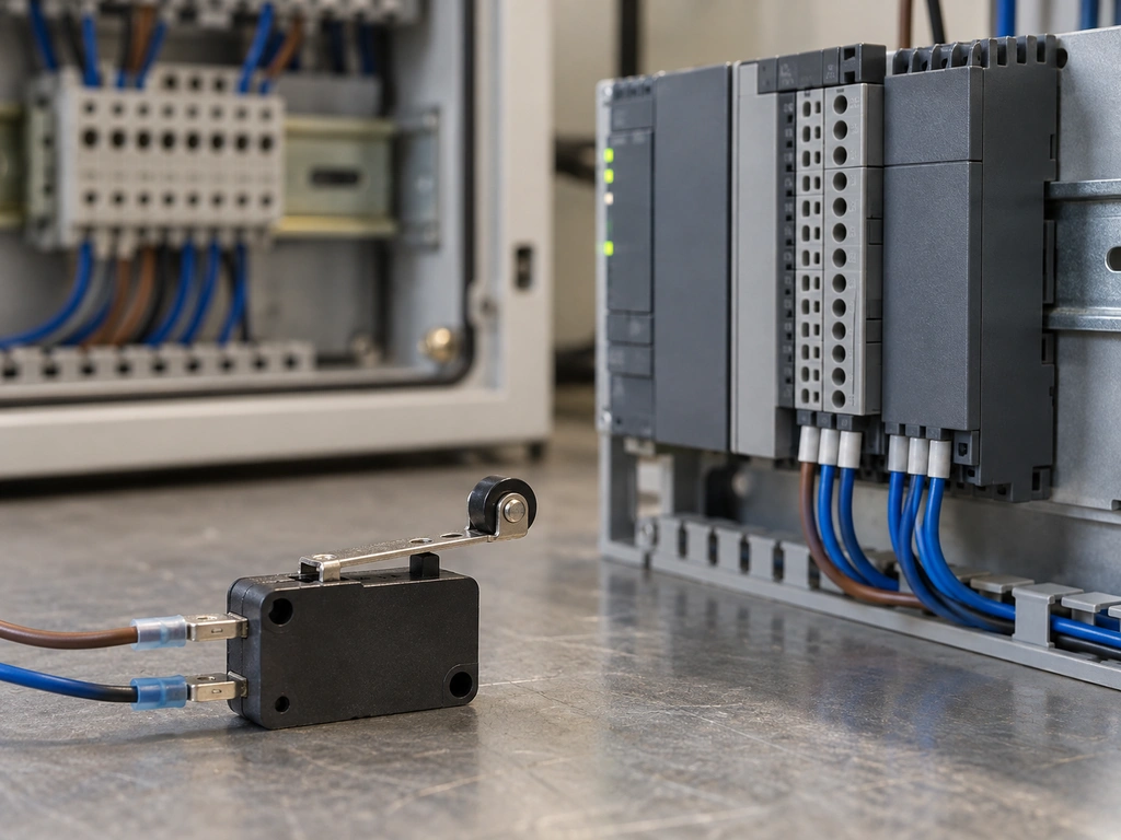
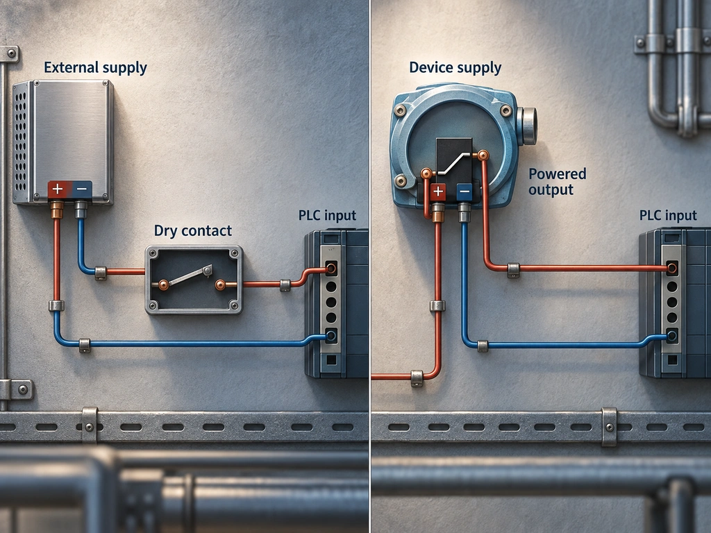
The difference between a dry contact and a wet contact is where the signal voltage comes from. A dry contact opens or closes a circuit powered elsewhere. A wet contact, as the term is used here, switches a signal powered by the field device.
Connecting either one to a programmable logic controller (PLC) requires a complete current path through the output, input, supply, and return. The wiring examples below use 24 V DC digital inputs. The connections for a particular installation must follow its input module diagram.
What Is a Dry Contact?
A dry contact is a switch or isolated relay contact that opens or closes an externally powered circuit. It supplies no voltage of its own. A micro switch can provide a dry contact if its voltage, current, and minimum-load ratings suit the PLC input. Once connected, its terminals may carry voltage from the external circuit.
What Is a Wet Contact?
A wet contact is a powered output that switches a signal using the device’s supply. For example, a PNP output drives the signal toward positive voltage, while an NPN output pulls it toward 0 V. The output’s voltage, polarity, current capacity, and reference connection must suit the PLC input.
How Sinking and Sourcing PLC Inputs Work
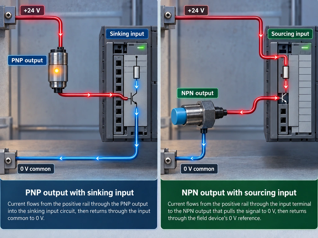
In the convention used for the examples below, a sinking input receives current from a positive field signal and returns it through a common connected to 0 V. A sourcing input supplies current through its sensing circuit; the field device completes the path to 0 V. A PNP output therefore pairs with a sinking input, and an NPN output with a sourcing input.
The names are not consistent across manufacturers. Rockwell calls an input sinking when positive voltage at its terminal turns it on. Mitsubishi’s FX3S manual calls an input sink when a contact connects the terminal to 0 V. Follow the current-path drawing and common-terminal instructions for the actual module, regardless of the name used.
How to Identify a Dry or Wet Contact
The five checks below establish what the output switches and which reference to use before connecting it to the PLC.
Step1: Check the Datasheet and Terminal Diagram
Identify the exact field device and PLC input model. On the output diagram, look for isolated COM/NO/NC contacts, transistor symbols, PNP or NPN labels, supplies, and shared commons. On the input diagram, find the voltage range, ON and OFF thresholds, sensing current, and any internal supply for contact sensing.
Step2: Isolate Power and Test Passive Contact Continuity
Disconnect the contact from other circuit paths. Isolate all power sources and verify that the circuit is de-energized before using the meter’s continuity mode. For a mechanical changeover contact, test COM–NO and COM–NC with the actuator at rest and operated. The closed pair should show continuity; the open pair should not. Continuity testing cannot establish whether an electronic output suits a PLC, and it must not be used on an energized or transistor output.
Step3: Confirm Test Points and Voltage Range
Find the signal terminal and its stated reference, such as 0 V or output common, on the device diagram. Determine whether to measure AC or DC, then choose a meter and range rated for the expected voltage. A reading between arbitrary terminals may miss a powered output.
Step4: Power the Device and Measure the Output
Reconnect and power the device as its manual specifies. Measure the output against its documented reference in both inactive and active states. A powered output should move toward its specified level when switched, though leakage or coupled voltage can appear on a high-impedance meter. Voltage alone does not prove that the output can supply enough current. Measuring across a closed contact is also inconclusive because its voltage drop is normally small.

Step5: Record the Interface Type and Reference
Record whether the output is an isolated passive contact, a PNP or NPN powered output, or another documented type. Note its supply, reference terminal, inactive state, and contact or output ratings. Resolve any conflict between the diagram and your measurements before connecting the PLC.
How to Wire Signals to PLC Inputs
These examples apply to DC input modules using the current-flow convention described above. Some dedicated dry-contact inputs provide their own sensing current and require only a closure across specified terminals. Do not add an external 24 V feed to such an input unless its manual calls for one.
Dry Contact to a Sinking Input
If the input common connects to 0 V and positive voltage turns the channel on, wire a protected +24 V supply through the dry contact to the input terminal. Closing the contact completes this path: +24 V → contact → input circuit → 0 V. Choose the NO or NC terminal according to the required resting state.
Before using an XSS-5 miniature micro switch as the dry contact, compare the exact model’s DC rating and minimum applicable load with the PLC input’s voltage and sensing current. .
Dry Contact to a Sourcing Input
If the input common connects to +24 V and pulling the channel toward 0 V turns it on, wire the dry contact between the input terminal and 0 V. When the contact closes, current flows from +24 V through the input circuit and contact to 0 V. A passive contact can work with either input arrangement if its ratings permit it; the common and contact connections change.
Powered Output to a Compatible PLC Input
Connect a PNP output to an input that accepts a positive signal. An NPN output needs an input that supplies current through its sensing circuit to the output and then to 0 V. Power the field device as specified, connect its output to the input point, and make the reference connections shown in both manuals. Compare the output’s on-state voltage, drive current, and off-state leakage with the input’s voltage range and ON/OFF thresholds.
Two supplies should not be joined simply because both are labeled 24 V. If their voltages, references, or input arrangements prevent a direct connection, use a suitably rated interposing relay or isolated interface.
How to Verify the PLC Input After Wiring
Operate the field device with the circuit energized under its normal test conditions. Check both the resting and operated states:
- Measure the voltage at the PLC input terminal against its documented common.
- Check whether the module’s input indicator changes.
- Check whether the corresponding input state changes in the controller.
If the terminal voltage changes but the indicator does not, check the common connection and input threshold. If the indicator changes but the controller state does not, check the channel address and input configuration. If the field voltage does not change, trace the output and return path.
Common PLC Signal Wiring Mistakes
Match the symptom to a likely cause. Check the PLC input and its common before tracing the field wiring.
| Symptom | Likely Cause | What to Check or Correct |
| Input never turns on | Open contact path, missing signal supply, or wrong common | Compare the closed-state voltage and current path with the module diagram. |
| Input stays on | Off-state leakage, incorrect NO/NC pair, or unintended feed | Compare the off-state signal with the input’s OFF threshold; trace any parallel path. |
| Fuse opens or input faults | Conflicting supplies or excessive input voltage | Isolate power, trace both supplies, and use a rated interface if they cannot be connected directly. |
| Several channels change together | Inputs bridged or an unintended shared return path | Check each channel’s field wire and the input-bank common against the module diagram. |
| Input flickers | Loose contact, inadequate low-load performance, or bounce | Inspect terminals and contact ratings; set an input filter only if the signal timing permits it. |
If you are assessing a replacement switch for a low-current input, send the existing model, contact arrangement, PLC input voltage and current, and operating conditions to XURUI to submit circuit specifications. Those details allow a model-specific compatibility review.
Frequently Asked Questions
Does a Dry Contact Have Voltage When It Is Wired?
Yes. An external circuit can place voltage on its terminals even though the contact generates none. An open contact may have voltage across it; a closed contact normally has only a small voltage drop. Identify the supply and reference before measuring.
Is a Relay Output Always a Dry Contact?
No. Relay describes how the output switches, not how its terminals are powered. The terminal diagram shows whether the contact pair is isolated or one side is connected to a supply. An isolated pair needs an external signal source.
Can One Dry Contact Be Shared by Two PLC Inputs?
Yes, if both input circuits are designed to share the same supply and reference and the contact can carry their combined sensing current. Otherwise, sharing the contact may join circuits that should remain separate. Use separate contact poles or interposing relays when isolation is required.
Is a Dry Contact the Same as a Normally Open Contact?
No. Dry describes a contact without a built-in voltage source. Normally open and normally closed describe its state when the actuator or relay is not operated. A dry changeover contact can provide both paths.
What Is the Difference Between a Wet Contact and Wetting Current?
A wet contact, as defined here, is a powered signal interface. Wetting current flows through a mechanical contact to help overcome surface films and maintain reliable conduction. The necessary current varies with contact construction and operating conditions; use the device’s minimum applicable load rather than a universal value.
External Sources
- MicroLogix 1000 Programmable Controllers User Manual
- FX3S Series Programmable Controllers User’s Manual
- Schneider Electric SEC-TE Installation Manual
- Fluke Guide to Continuity Testing
- Omron General Application of Switches
- Analog Devices ADE1201 Data Sheet






