
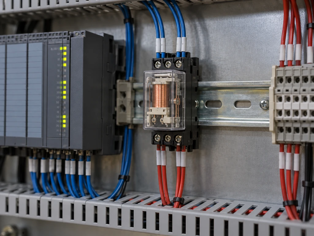
An interposing relay sits between a controller and a field circuit. In a common PLC arrangement, the PLC output energizes the relay coil, and the contacts switch the load circuit. “Interposing” describes the relay’s position and role in the circuit, not one specific construction.
The contacts can switch a separately powered load at a different voltage, but the relay does not convert voltage or increase the PLC output’s capacity.
How Does an Interposing Relay Work?
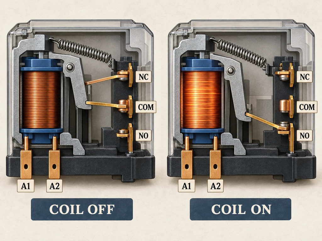
In a typical electromechanical relay, the PLC energizes coil terminals A1 and A2. The coil’s magnetic field pulls an armature and changes the contact state. On a single-pole, double-throw relay, COM (common) connects to NC (normally closed) while the coil is off. When energized, COM switches to NO (normally open). A spring returns the contacts when the coil loses power.
The contacts carry current from the field circuit’s supply, not through the PLC output transistor. The coil and contacts are separate circuits, with electrical separation set by the relay’s insulation ratings.
When Should You Use an Interposing Relay?
Use an interposing relay when the PLC output cannot switch the field load directly or when the circuit needs extra contacts or isolation. The output must still be able to drive the coil. If its ratings cover the load’s voltage, current, inrush, and switching duty, and the circuit already has the required contacts and isolation, direct control is generally sufficient.
Control-to-Load Voltage Mismatch
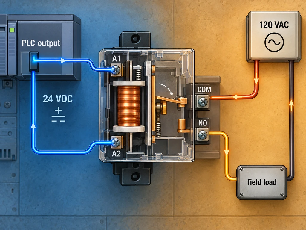
A 24 VDC PLC output can energize a compatible relay coil while the contacts switch a separately powered 120 VAC circuit. The coil and contacts must each be rated for their respective circuits.
PLC Output Capacity Limits
When load current or switching characteristics exceed the PLC output’s rating, a relay lets the output command a separate load circuit. The PLC output still has to supply the coil’s pickup and operating current. If it cannot, use a suitable interface or driver.
Isolation and Additional Contact Requirements
An interposing relay can electrically separate the control and field circuits or add contacts the PLC output does not have. Check its insulation ratings against both circuits. Isolation alone does not make a standard relay suitable for a safety function or protect every circuit from every fault.
Where Are Interposing Relays Used?
In PLC and DCS panels, interposing relays connect controller outputs to field devices, repeat status signals, and support interlocking circuits.
PLC/DCS Outputs to Field Devices
A PLC output may energize an interposing relay whose contacts switch a contactor coil, solenoid valve, or pilot device. In motor control, the relay usually commands a contactor or starter. Its contacts should switch motor power only if they have a verified rating for that load and duty.
For AC loads suited to semiconductor switching, a solid-state relay (SSR) can provide a similar controller-to-load role.
Status Feedback to Control Systems
A relay can repeat the state of a field switch or device to a PLC or DCS input. The returned contact reports the signal it monitors; it does not confirm that a downstream load has operated.
Relay-Assisted Interlocking
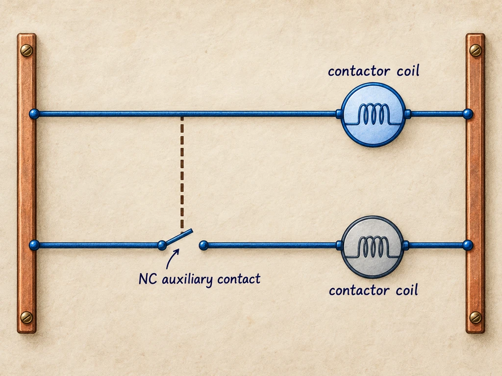
Relay contacts can add permissives to a control circuit. For example, a normally closed auxiliary contact from one contactor can interrupt the other contactor’s coil circuit, preventing both from energizing at once.
How Should PLC Engineers Select an Interposing Relay?
Start with the coil requirements for the PLC output and the contact ratings for the field load. Then confirm the contact arrangement and isolation ratings.
Match Coil Requirements
Match the coil’s nominal voltage and AC or DC type to the PLC output. Make sure pickup and operating current fit within the output-point and shared module limits. Check whether the output sources or sinks current, and whether the relay’s suppression circuit affects compatibility or release time.
Verify Load-Side Ratings
Check the contact voltage and current ratings for the load’s normal current, inrush, and switching duty. Motors, solenoids, and contactor coils are inductive loads, so they can stress contacts differently from heaters.
Confirm Contact Form and Isolation Rating
Count the poles and identify the required NO, NC, or changeover contacts. Compare the relay’s working and insulation ratings with the control and field circuits. A dielectric test voltage represents a test condition, not the continuous working voltage. Also confirm that the relay suits the panel’s mounting and environmental conditions.
Getting the PLC-to-Field Interface Right
To assess an AC application for solid-state switching, send the PLC output type, load voltage and current, load type, switching frequency, and enclosure temperature to XURUI’s technical team.
Frequently Asked Questions
Can an SSR Replace an Interposing Relay When a Dry Contact Is Required?
No. An SSR does not provide volt-free mechanical contacts. It switches through semiconductor devices, has no mechanical COM, NO, or NC contacts, and may pass a small current when off. The XSSR-W6 series includes AC-output models; check the current model-specific datasheet for off-state leakage before using one in a circuit sensitive to leakage.
What Causes an Interposing Relay to Chatter?
Coil-voltage fluctuations or a drop below the relay’s operating requirement can cause chatter. Measure voltage at the coil while the fault occurs, inspect the control-circuit connections, and check for drops when nearby loads start. Confirm that the PLC output is not pulsing. Keep coil voltage within its rating.
How Can You Test an Interposing Relay?
Isolate the circuit and verify that it is de-energized before checking continuity. Check the coil for an open circuit, then test the contacts at rest. On a standard, non-latching changeover relay, COM–NC should be closed and COM–NO open while the coil is off. A controlled functional test with rated coil voltage should make the contacts transfer.
How Often Should an Interposing Relay Be Replaced?
There is no universal replacement interval. Compare the relay’s mechanical and electrical life ratings with the actual load, inrush, switching frequency, and temperature. Replace it according to the manufacturer’s limits or if it chatters, fails to operate, has welded contacts, or overheats.
External Sources
- Rockwell Automation, High-Density Interposing Applications
- Phoenix Contact, PLC-RPT Relay Module Technical Data
- OMRON, General-Purpose Relay Troubleshooting
- Rockwell Automation, Lacking Safety in Interposing Relay Applications?






