

A prox switch symbol marks a device that detects a nearby object without contact and changes an electrical output. Labels and terminal connections identify the sensing method and show how that output behaves in the circuit.
This guide covers common symbol cues and ways to trace sensor outputs. Drawing conventions vary, so use the legend, device tag, and terminal labels together.
What Is a Proximity Switch Symbol?
A proximity switch symbol marks noncontact detection with a discrete output. A limit switch is mechanically actuated; a general sensor symbol may instead represent a continuous measurement. Nearby labels and terminal connections identify the sensing technology and output.
How to Read a Proximity Switch Symbol
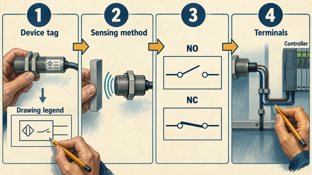
Start with the device tag and drawing legend. Identify what actuates the device, read whether its output is normally open (NO) or normally closed (NC), and trace its terminals to the load or controller. NO and NC describe the output’s normal state; PNP and NPN describe the transistor output type.
On a multi-sheet drawing, wire numbers and cross-references may continue the circuit elsewhere. The same approach helps when reading an electrical panel wiring diagram.
Proximity Switch Symbols by Technology Type
The sensing method identifies what can trigger the device. The output terminals show how it signals that detection. Magnetic reed switches use contacts, while the electronic sensor types below use electronic outputs.
Inductive Proximity Sensor Symbol
An inductive sensor detects metal when it changes the electromagnetic field at the sensing face. A drawing may use coil imagery or an “inductive” label. A coil-like mark alone can be ambiguous, so check the device tag and legend. Read the NO or NC state separately.
Capacitive Proximity Sensor Symbol
A capacitive sensor responds to a change in capacitance near its sensing face and can detect metal and many nonmetal targets. Drawings may use a pair of plates or a “capacitive” label. The symbol does not specify a target’s sensing distance or whether the sensor can detect it through a wall.
Magnetic Reed Switch Symbol
A magnetic reed switch symbol shows a contact operated by an approaching magnet. Read the contact’s open or closed state and look for a magnet or magnetic actuation mark. A bare reed contact has no PNP or NPN output. The XGH Series reed switch is one example of this magnetically operated contact type; use the exact model’s contact drawing to identify its configuration.
Photoelectric Sensor Symbols
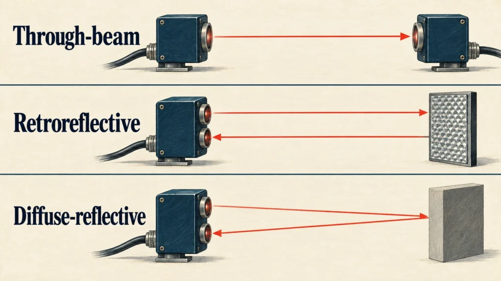
Photoelectric symbols show detection by light. An emitter and receiver facing each other indicate through-beam sensing. A reflector indicates retroreflective sensing, while light reflected from the target indicates diffuse-reflective sensing. Check the label and output state to determine whether the sensor switches when light reaches the receiver or when the beam is blocked.
Ultrasonic Proximity Sensor Symbol
An ultrasonic sensor detects a target from reflected sound. Drawings may show outgoing and returning wave marks or label the device “ultrasonic.” These cues identify the sensing method, not the operating distance or output type. Terminal labels show whether it provides a switched signal, an analog measurement, or both.
How Proximity Switch Wiring Is Shown in Schematics
The symbol identifies how the device detects a target; the wiring shows its power and signal paths. Count the conductors, then trace each labeled terminal to its connection.
Two-Wire and Three-Wire Sensor Wiring
A two-wire electronic sensor connects in series with its load. The same two conductors carry operating power and switched current, so its specified OFF-state leakage and ON-state voltage drop can affect a controller input. A bare two-lead reed switch is a contact and does not need operating power.
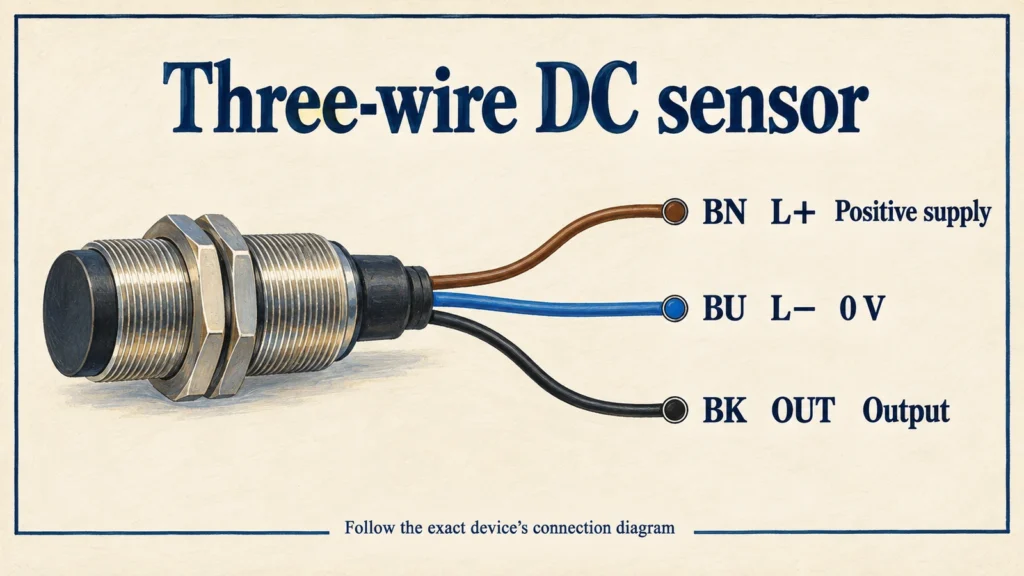
A three-wire DC sensor has separate positive supply, 0 V supply, and output connections. The drawing shows the sensor’s power path separately from the signal sent to the controller input.
PNP and NPN Output Markings
PNP and NPN identify the output’s current path. When active, a PNP output sources current toward the positive supply and pairs with a sinking input. An NPN output sinks current toward 0 V and pairs with a sourcing input. Trace the PNP and NPN wiring through the controller input’s common terminal to confirm the match. A voltage label alone does not show the common polarity.
Typical Wire Colors and Terminal Markings
Many three-wire DC sensors use brown (BN) for positive supply, blue (BU) for 0 V, and black (BK) for output. Schematics may instead show L+, L−, OUT, or connector pin numbers. Follow the exact device’s connection diagram because assignments can vary.
These color conventions do not apply to bare reed contacts, so check the switch’s connection diagram to identify its leads. If you’re unsure which reed switch fits your circuit, share your schematic with XURUI for help with selection.
FAQs
Does a Proximity Switch Symbol Show Its Sensing Distance or Target Material?
No. The symbol identifies the device’s function and may show its technology, but it does not give the operating distance or a qualified target. Find those details in the model’s specifications, including the stated test target. For a reed switch, magnet strength and orientation also affect the switching point.
How Do IEC 60617 and IEC 60947-5-2 Differ in Proximity-Switch Symbolization?
IEC 60617 provides graphical symbols for electrical diagrams; IEC 60947-5-2 sets requirements for covered proximity-switch products. Use IEC 60617 to interpret a drawing symbol. IEC 60947-5-2 addresses product characteristics and tests, not the circuit’s connection details. Its magnetic-device scope covers nonmechanical magnetic proximity switches, so do not assume it applies to a bare mechanical reed contact.
How Are Analog-Output Proximity Devices Represented Differently from Discrete Proximity Switches?
An analog-output device is marked with a varying signal range, such as 4–20 mA or 0–10 V, instead of only an NO or NC state. Some devices provide both analog and discrete outputs; trace each terminal to its controller input. The model documentation defines the signal range and the distance or position it represents.
External Sources
- IEC 60617:2026 DB — Graphical Symbols for Diagrams
- IEC 60947-5-2:2019 — Proximity Switches
- OMRON — Overview of Proximity Sensors
- OMRON — Overview of Photoelectric Sensors
- Schneider Electric — Inductive Proximity Sensor Technical Information
- Banner Engineering — D10 Expert Sensor with Analog and Discrete Outputs






