
A reed relay can fail early when its contacts switch an unprotected inductive load, lamp inrush, or a signal below the specified minimum load. An undersupplied coil can also chatter or release late. Steady-state current alone does not expose these risks.
This guide explains how a reed relay switch moves from coil input to contact output, where the design fits, and which electrical and mechanical checks prevent a poor match. It also separates a complete reed relay from the reed switch element used inside one.
What Is a Reed Relay Switch?
A reed relay switch is an electromagnetic relay that uses a coil to operate reed contacts hermetically sealed in a glass tube. When current flows through the coil, the magnetic field closes or transfers the contacts. The coil circuit and contact circuit remain electrically separate within the relay’s rated insulation limits.
How Does a Reed Relay Switch Work?
A reed relay works by converting coil current into a magnetic field that moves sealed contacts. The coil and contacts are galvanically separate. The datasheet still controls dielectric strength, insulation resistance, and contact-to-coil capacitance.
Coil Energization
When the control circuit applies the rated coil voltage, current flows through the winding and creates a magnetic field. The field gives the facing reed tips opposite magnetic poles, so the tips attract and close. In a changeover relay, the common blade transfers between contacts.
The pickup point depends on coil power, resistance, temperature, and the relay’s magnetic design. If the reed relay coil voltage at the pins falls below the specified pickup level, the contact may stay open or chatter. A coil driven above its rating can overheat and shorten relay life.
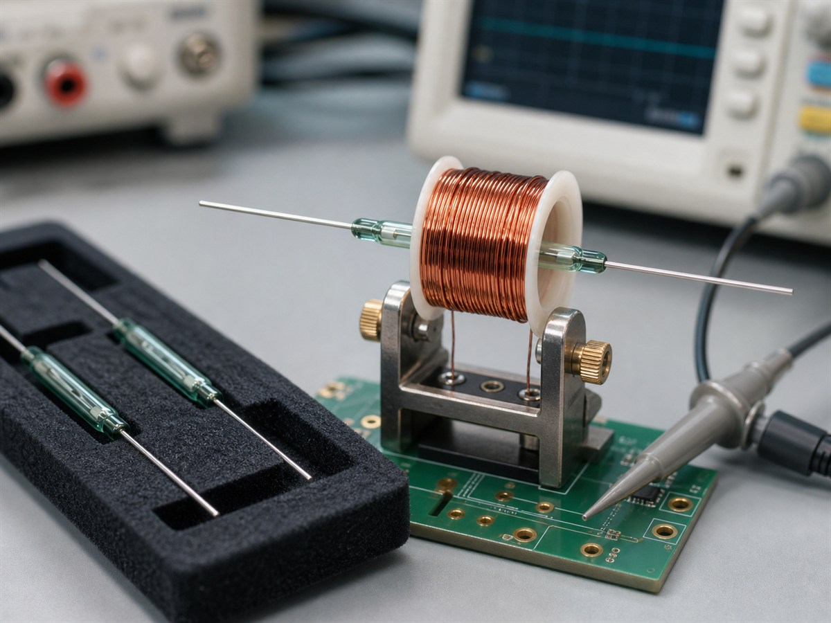
In a custom coil design, the reed element’s ampere-turn sensitivity sets the magnetic force needed to operate the contact. The finished relay still needs pickup and release tests because coil geometry changes the field at the reed.
Contact Operation and Release
The contact stays closed while the coil field holds the reeds together. When the driver cuts coil current, the field decays and the elastic reeds separate. Reed contacts have low moving mass, but relay construction and coil suppression still control the release time.
Contact bounce can occur during closing or opening. A logic input may need debounce time or a controlled sampling window. A precision measurement path also needs verified operate time, contact resistance during switching, capacitance, leakage, and thermal EMF.
Coil Circuit and Contact Circuit
The coil circuit operates the relay. The contact circuit carries the switched signal or load. Rate both sides separately.
- For the coil circuit, check drive current, polarity, suppression, and turn-off behavior.
- For the contact circuit, check voltage type, steady current, inrush, load category, and minimum signal level.
A 5 VDC or 24 VDC coil rating does not define contact capacity.
Where Are Reed Relay Switches Used?
Reed relays fit test paths and low-power control circuits that need compact, electrically isolated contacts. The open-contact voltage, closing current, signal level, switching rate, and nearby magnetic fields determine whether the relay fits the circuit.
Automated Test and Measurement Paths
Automated test equipment uses reed relays to connect instruments, test points, sensors, and calibration paths under software control. The glass capsule isolates the contact surface from the surrounding atmosphere. Selecting a reed relay for test and measurement still requires checking contact resistance stability, thermal EMF, leakage, capacitance, and switching time.
PCB layout can change signal integrity. Trace spacing, adjacent coils, cable capacitance, and instrument input impedance all affect the result. A relay that passes a continuity test may still distort a low-level analog or high-frequency signal.
Low-Power Control and Sensing Circuits
Reed relays also switch alarm loops, low-power control paths, and sensing circuits when a controller needs a dry contact.
With a magnetic reed switch, a nearby magnet supplies the field that closes the contacts. A reed relay uses a coil for the same job. Sensor sensitivity therefore depends on magnet grade, air gap, alignment, and nearby steel.
What Limits a Reed Relay Switch?
The lowest applicable contact, coil, insulation, timing, or frequency rating limits a reed relay. Steady current covers only one part of the load. A short surge can weld the contacts, while a small measurement signal can expose resistance, leakage, or thermal EMF that a power test misses.
Contact Voltage, Current, and Switching Power
A reed relay contact rating combines voltage, switching current, switching power, and load type. A relay may list separate maximum voltage and current values, but the contact may not switch both maxima together. Use the rating table for the actual circuit.
DC loads can sustain an arc because the current does not cross zero each cycle. Capacitive loads can produce a sharp charging current when the contact closes. A resistive-load rating does not qualify either condition.
Coil Operating Range and Release Behavior
The coil must pick up across the full supply range after driver voltage drop and wiring loss. Copper resistance rises with temperature, so coil current falls at a fixed voltage. A small drive margin can cause slow operation or missed pickup at high temperature.
Reed relay coil suppression protects the DC driver at turn-off. A conventional flyback diode uses a low clamp voltage, which slows field decay. Check the driver’s voltage limit and the required release time before choosing the suppression circuit.
Inrush and Inductive Loads
Inductive loads store energy that raises contact voltage when the circuit opens. Lamps and capacitive inputs can draw far more current at closure than during normal operation. Both conditions can pit, stick, or weld a reed contact that passes a steady-current check.
Match protection to the circuit:
- Use a diode or a controlled voltage clamp for a DC inductive load.
- Use an RC snubber, TVS device, or varistor only where its voltage and energy ratings fit the circuit.
- Limit lamp or capacitive inrush with series impedance when the load permits it.
Test the finished circuit at the specified worst-case voltage, current, temperature, and switching rate. A protection part does not raise the relay’s published contact rating.
Low-Level Signal and High-Frequency Limits
Low-level signal switching with a reed relay depends on stable contact resistance, low leakage, and controlled thermal EMF. For microvolt or microamp signals, check for a stated low-level or minimum-load specification. A power rating alone does not qualify a precision measurement path.
At higher frequencies, open-contact capacitance, lead inductance, shielding, and PCB geometry affect insertion loss and crosstalk. Use an RF-rated relay when the signal exceeds the validated bandwidth of a standard package. Test the assembled board with the intended cables and instruments.
How Should Buyers Select a Reed Relay Switch?
To select a reed relay, match the controller output, switched load, signal requirements, and package data. Record these values before comparing part numbers. A complete application record gives Xurui Switch the core inputs used to compare a standard XGH request with a custom reed-element specification.
Matching the Controller Output
Record the nominal coil voltage, worst-case supply, available drive current, and release-time limit. A transistor output also needs the correct suppression polarity and clamp voltage. When one output drives multiple coils, add their maximum coil currents and stay within the controller rating.
Matching the Switched Load
Document the maximum open-contact voltage, normal current, inrush current, load type, switching rate, and required life. Compare each value with the applicable datasheet rating. Current alone cannot qualify the contact.
| Check | Why it matters | Data to confirm |
|---|---|---|
| Open-contact voltage | Sets dielectric and arc stress | Peak AC and DC voltage |
| Current at closure | Captures lamp and capacitive inrush | Peak current and duration |
| Current at opening | Sets contact erosion risk | Load type and suppression |
| Signal level | Protects measurement quality | Minimum voltage and current |
| Switching duty | Affects contact wear and heat | Cycles per hour and ambient temperature |
After the load check, reed switch selection depends on tube size, contact form, magnetic sensitivity, and installation conditions. These magnetic and mechanical checks sit outside the contact load limits.
Confirming the Package and Replacement Data
For a reed relay replacement, confirm pin layout, coil resistance, contact form, mounting style, package height, and board footprint. A similar package may use different coil pins or contact terminals. Different magnetic shielding can also change interaction with adjacent relays.
Test the candidate relay in the full circuit across the expected temperature and load range. Measure pickup voltage, release voltage, contact resistance under load, and release time. Use the production suppression parts, PCB spacing, and enclosure during qualification.
Xurui groups its current XGH options in the reed switch product range. The selected XGH model still needs the correct tube dimensions, contact rating, and magnetic sensitivity.
Specifying a Reed Switch for a Custom Relay Design
A custom reed relay starts with the reed element. The designer then matches the coil and magnetic circuit to the required operate and release values. The specification should state contact form, tube size, contact rating, magnetic sensitivity, lead style, coil envelope, and insulation target.
The XGH Series Reed Switch includes normally open and changeover contacts for magnetic sensing or use as a reed-relay element. The relay designer must match the tube size and ampere-turn value before setting the coil geometry.
FAQs
Can a Flyback Diode Delay a Reed Relay’s Release Time?
Yes. A diode across a DC coil gives current a low-voltage path after the driver turns off. The magnetic field then decays more slowly, which increases release time. Select the suppression circuit only after checking the release-time requirement and the driver’s voltage limit.
Why Might a Reed Relay Fail to Reset After Coil Power Is Removed?
A reed relay may stay closed because the contacts have welded, the coil still carries current, or a nearby magnetic field holds the reeds together. Measure voltage across the coil after turn-off. Then isolate the load and check contact continuity with nearby magnetic sources removed.
Can Nearby Magnets, Transformers, or Relays Affect a Reed Relay?
Yes. Magnetic interference from nearby reed relays, magnets, or transformers can shift pickup or release behavior. Follow the manufacturer’s spacing guidance. If the manufacturer gives no spacing, test the final layout and add magnetic shielding when the results require it.
Can Ultrasonic Cleaning Damage a Reed Relay?
Ultrasonic cleaning can change reed-relay characteristics because strong vibration stresses the reed element and package. Follow the relay manufacturer’s cleaning limits. If the datasheet gives no approved process, validate washed samples before releasing production.
How Should a Reed Relay Be Tested in a Finished Circuit?
Measure coil voltage at the relay pins, then check the contact state with the coil on and off. Test contact resistance or voltage drop under the real load after applying the required safety controls. A bench continuity check cannot expose inrush stress, delayed release, or measurement error.
XURUI Engineering Team






