
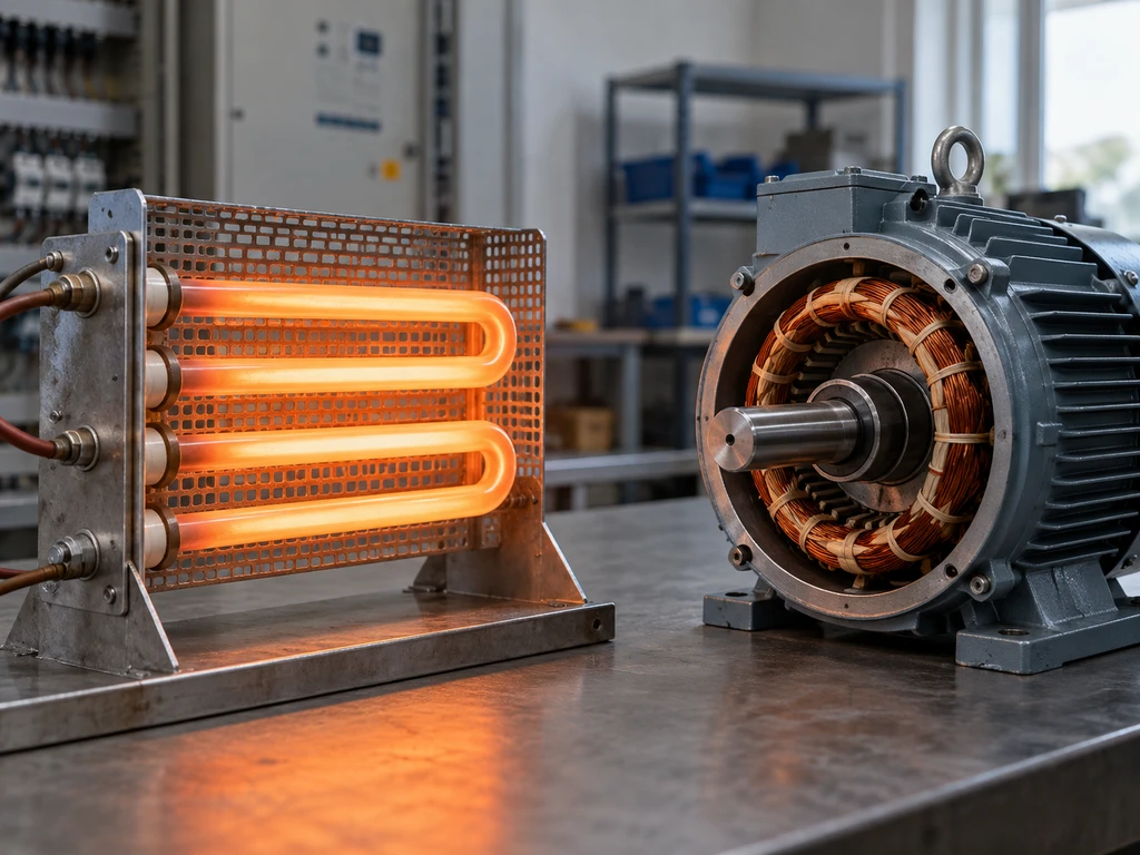
The main difference between an inductive load and a resistive load is how each uses electrical energy. A resistive load converts power mainly into heat or light. An inductive load creates a magnetic field and causes current to lag voltage in a sinusoidal AC circuit.
This difference affects current calculations, power factor, startup behavior, switching ratings, and transient protection. Correct load classification helps prevent contact damage, overheating, nuisance trips, and undersized components.
What Are Resistive and Inductive Loads?
Resistive and inductive loads are classified by their dominant electrical behavior. Real equipment can have both properties, so the classification describes the primary characteristic rather than a perfectly pure circuit.
Resistive Loads and Common Examples
A resistive load opposes current through resistance and converts electrical energy mainly into heat. In an ideal resistive AC circuit, current and voltage are in phase, reactive power is zero, and the power factor is 1.
Examples include fixed resistors, resistance ovens, heating elements, soldering irons, and incandescent lamp filaments. An appliance that produces heat is not necessarily a purely resistive load. Electronic controls or power supplies can change its input behavior.
Inductive Loads and Common Examples
An inductive load creates a magnetic field through a coil or winding. It opposes sudden current changes, and its current lags voltage when inductive behavior dominates in a sinusoidal AC circuit. Motors, transformers, solenoids, contactor coils, relay coils, and electromagnetic valves are common examples. These loads combine winding resistance with inductance, so their operating current, starting current, and switching transients must be considered separately.
Key Differences Between Inductive and Resistive Loads
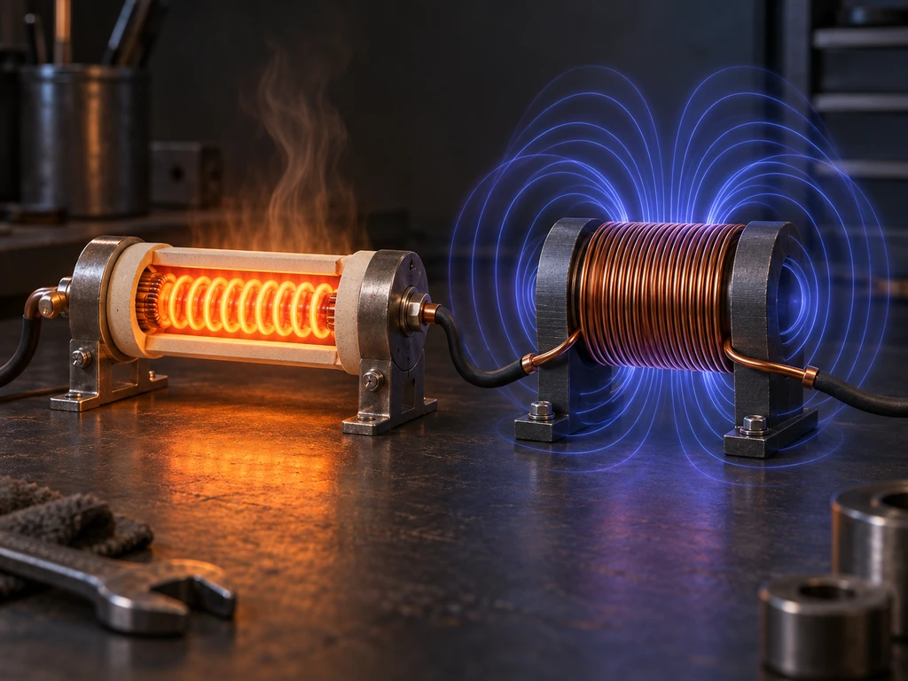
The practical differences involve energy storage, phase angle, startup current, and switching stress. These effects explain why the same current rating may not apply to both load types.
Energy Conversion and Magnetic Energy Storage
A resistive element dissipates electrical energy as heat:
P = I² × R
A linear inductor stores energy in its magnetic field:
E = ½ × L × I²
When the current path opens, the magnetic field collapses and releases this energy. Inductive loads therefore need more careful suppression and switching control. Available solid state relay families treat load type, surge behavior, thermal design, and protection as separate selection inputs.
AC Phase Relationship and Power Factor
In an ideal resistive AC circuit, current follows voltage without a phase shift. Real power and apparent power are equal, so the displacement power factor is 1.
In a linear inductive AC load, current lags voltage. The phase shift lowers displacement power factor, so the source and conductors carry more current than the watt value alone suggests. Electronic controls can also distort the current waveform, which means total power factor cannot always be determined from phase angle alone.

Startup and Inrush Characteristics
A stable resistive element often has predictable current based on its operating resistance. Cold filaments and some heating elements can draw more current at startup because their resistance changes with temperature.
Motors and transformers can draw substantial inrush before normal magnetic and mechanical conditions develop. The magnitude and duration depend on equipment design, supply impedance, switching angle, mechanical load, and starting method. Use the manufacturer’s starting-current, locked-rotor, or inrush data instead of applying a universal multiplier.
Switching Transients and Their Effects on Switching Devices
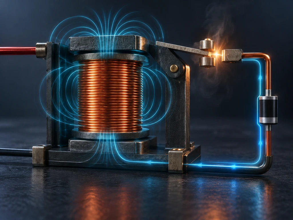
Opening an inductive circuit forces the stored magnetic energy to find another path. For an ideal inductor:
|V| = L × |ΔI ÷ Δt|
A rapid current change can therefore produce a high transient voltage. This can cause contact arcing, erosion, insulation stress, false triggering, or semiconductor failure. The guide to common reed-switch failure causes shows how inductive transients and excessive switching power can damage small mechanical contacts.
How to Calculate Load Current for Resistive and Inductive Loads
Load calculations begin with the supply type, voltage, real input power, efficiency, and power factor. Use nameplate values when they describe the actual operating condition.
Calculate Resistive Load Current and Power
For a single-phase resistive load:
I = P ÷ V
P = V × I
P = I² × R
P = V² ÷ R
A 2,000 W heater operating at 230 V draws:
I = 2,000 ÷ 230 = 8.70 A
This result assumes that 2,000 W is the electrical input power at 230 V and the element has reached its specified operating resistance.
Calculate AC Load Current Using Power Factor
For a single-phase AC load whose stated power is electrical real power:
I = P ÷ (V × PF)
For a balanced three-phase load:
I = P ÷ (1.732 × Vₗ × PF)
If the stated power is mechanical output, include efficiency:
I = Pout ÷ (1.732 × Vₗ × PF × efficiency)
These formulas estimate steady-state current. They do not calculate motor starting current or transformer energization inrush.
Compare Watts and Volt-Amperes in Load Sizing
Watts (W) measure real power converted into work or heat. Volt-amperes (VA) measure the apparent power carried by the supply:
VA = V × I
PF = W ÷ VA
A 1,000 W load at a power factor of 0.80 draws 1,250 VA. Final sizing must also account for inrush, harmonics, duty cycle, and temperature.
How to Identify Resistive and Inductive Loads?
Identify the load by combining its operating principle, documented ratings, and measured behavior. A visual inspection or resistance measurement alone cannot classify every mixed or electronically controlled load.
Identify the Load by Its Operating Principle
Equipment that produces heat through a resistance element is usually dominated by resistance. Equipment that creates motion, magnetic force, voltage transformation, or an electromagnetic field is usually inductive. Inspect the complete input circuit. A heater controlled by a drive, rectifier, or switching power supply can present a different load to the upstream switch than the heating element presents internally.
Check the Nameplate and Datasheet
Look for input voltage, phase, frequency, current, watts or kilowatts, VA or kVA, power factor, efficiency, locked-rotor current, inrush current, and duty cycle. For coils, check AC or DC operation and the specified pickup, holding, or sealed power.
Also check the switching-device datasheet for separate resistive, motor, pilot-duty, or utilization-category ratings. A general current rating without its applicable load category is not enough for final selection.
Test the Load Characteristics
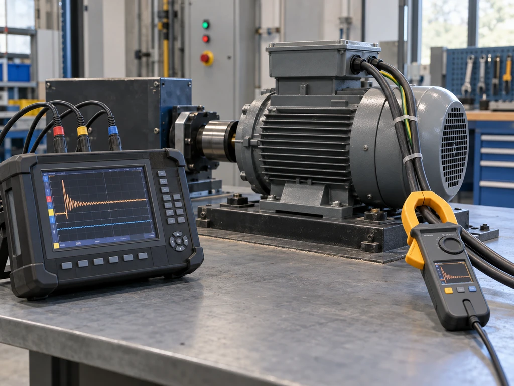
Use appropriately rated instruments and safe procedures to measure RMS voltage, RMS current, real power, apparent power, power factor, and startup current. A power analyzer can distinguish phase displacement from waveform distortion.
An unpowered resistance measurement may reveal an open winding or shorted element, but it cannot establish power factor or operating inrush. Compare measured results with the nameplate limits and record the highest current during the actual duty cycle. The solid state relay selection guide provides related checks for load current, switching method, heat removal, and protection.
How to Select a Switching Device for Each Load
Select a switching device by its load-specific making, carrying, and breaking capability, not only by its headline current rating. Protection and operating conditions are part of the selection.
Define the Voltage, Current, Inrush, and Switching Duty
Document the supply type, operating voltage, steady RMS current, measured or specified inrush, switching frequency, duty cycle, ambient temperature, and expected fault conditions. State whether the device starts a motor, interrupts a running motor, switches a coil, or controls resistance heating.
These duties impose different stresses even when their steady-state currents match. Frequent reversing or inching, for example, requires a different contactor utilization category from normal motor starting and stopping.
Compare Mechanical Switch, Relay, Contactor, and SSR Ratings
Mechanical switches can provide direct manual control when their load-specific contact rating covers the duty. Electromechanical relays handle control circuits and moderate loads but need appropriate motor, pilot-duty, or inductive ratings.
Contactors are designed for repeated power switching and are selected by operational current, utilization category, coil specification, and required endurance. SSRs support silent and frequent switching, but they produce on-state heat and may pass off-state leakage current. This normal relay and solid state relay comparison explains their operating differences.
Add the Correct Suppression and Protection
A reverse-biased flyback diode can clamp the turn-off voltage of a DC coil, but the slower current decay may delay release. A TVS diode or another clamp may be more suitable when release time matters.
For AC inductive loads, use an RC snubber, varistor, or other overvoltage protection that matches the circuit voltage, stored energy, allowable leakage, and switching device. Coordinate overcurrent protection with conductor limits and the device’s fault-withstand capability. Semiconductor outputs may require a fast fuse specified for the selected SSR.
Verify the Selection Under Worst-Case Conditions
Verify operation at the highest supply voltage, maximum ambient temperature, minimum cooling, greatest expected inrush, highest switching rate, and most demanding load state. Measure contact behavior or semiconductor temperature during a representative operating cycle.
Confirm the exact datasheet, utilization category, derating curve, transient rating, heatsink calculation, and approval scope. Product-family information can support initial screening, but it cannot confirm the final operating margin. For example, the XSSR-W2 single-phase solid state relay must still be verified at the model level for control input, load voltage, switching method, current, cooling, and protection.
Find the Right Switch, Relay, Contactor, or SSR for Your Load
Select the device from its load-specific rating, inrush capacity, switching duty, protection requirements, and thermal conditions. Contact XURUI with these details for model review.
External Sources
- DOE Electrical Science Handbook
- Fluke 434/435 Users Manual
- Schneider Electric TeSys Technical Information







