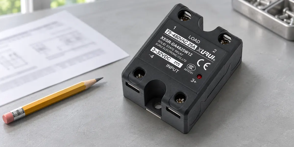
A solid state relay symbol shows the control input and semiconductor switching path. To distinguish DC-AC, DC-DC, and AC-AC types, read the configuration as control input first, switched load second. Simplified drawings may omit this information, so confirm the complete model’s ratings before wiring.
This guide explains the drawing clues for each type and how to match them to the terminals on panel-mounted and PCB-mounted SSRs.
What a Solid State Relay Symbol Shows
A solid state relay switches a load electronically, without moving contacts. Its symbol may show the internal components or use a labeled block.
In a detailed drawing, identify:
- The control terminals that receive the switching command.
- The output semiconductor that controls load current.
- The isolation path, if shown. In an optically isolated design, an LED sends light to a receiver across an electrically separate barrier.
The drawing’s purpose matters. A schematic symbol shows the device’s circuit function; an internal equivalent circuit explains its structure; a terminal diagram maps connections to the physical device. A simple SSR block may show the function without identifying the output technology, electrical limits, or isolation rating.
How DC-AC, DC-DC, and AC-AC SSR Types Differ
In this guide, the first term describes the control signal and the second describes the load supply. A DC-AC SSR uses DC control to switch externally supplied AC power. It does not convert DC into AC.
The following clues describe common designs. Use them to interpret the circuit, then confirm the stated ratings.
| SSR Type | Control Input | Switched Load | Typical Diagram Clues | Required Confirmation |
| DC-AC | DC | AC | Polarized input; TRIAC or inverse-parallel SCR output | DC input range and current; AC load ratings |
| DC-DC | DC | DC | Polarized input; transistor or MOSFET output | Input requirements; DC output ratings and polarity |
| AC-AC | AC | AC | AC-marked input or input rectifier; TRIAC or inverse-parallel SCR output | AC input voltage and frequency; AC load ratings |
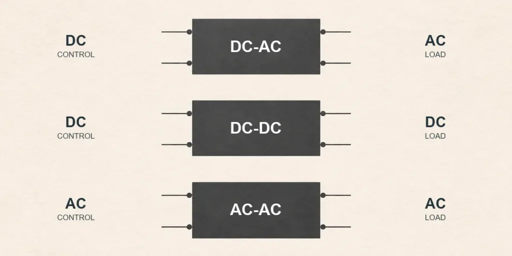
Other configurations exist. Some SSRs accept both AC and DC control signals, and some can switch both AC and DC loads.
DC-AC SSR Symbols
On a DC-AC drawing, the control side may show positive and negative terminals, an LED, and current-limiting components. The output commonly shows a TRIAC or two silicon-controlled rectifiers (SCRs) connected in inverse parallel. A TRIAC switches current in both directions; the SCR pair uses one device for each direction.
This configuration suits a DC controller switching an AC heater when the relay’s electrical and thermal ratings match the load. A TRIAC/SCR output generally cannot switch off a steady DC load reliably. After the trigger is removed, load current must fall below the holding current, the minimum that keeps the device conducting. Otherwise, the load may remain energized.
DC-DC SSR Symbols
A DC-DC drawing commonly shows a transistor or MOSFET at the output. A MOSFET is a voltage-controlled semiconductor switch. In a directional output, the device orientation and polarity marks indicate the permitted current path.
This configuration is a starting choice for a DC controller switching a DC solenoid or lamp. Check input and output polarity separately, along with the model’s reverse-current behavior. A correct control connection does not establish that the load side is wired correctly.
AC-AC SSR Symbols
An AC-AC drawing identifies AC at both the external control input and the load circuit. The input may contain a rectifier that supplies a fixed-polarity signal to the internal electronics, including an LED.
An internal LED therefore does not establish that the module requires DC control. Nor does a rectifier alone establish the permitted input supply. Read the external input rating. The output may use the same TRIAC or SCR arrangement as a DC-AC relay. Distinguish these two types by their control inputs, even when their load ratings match.
What the Symbol Alone Cannot Confirm
A MOSFET symbol does not necessarily indicate a DC-only output. Two MOSFETs connected back-to-back can switch in both directions, allowing suitably rated models to control AC or DC loads. That load capability remains separate from the input’s control requirements.
The drawing may also omit operating limits needed for selection:
- Input voltage and current thresholds for turning on and off.
- Zero-cross or random-turn-on operation. Zero-cross models wait until the AC voltage is near zero before turning on; random-turn-on models do not impose that delay.
- Continuous current, startup surge, minimum load current, and off-state leakage.
- Heat-sink requirements, ambient temperature limits, and protection components.
A missing zero-cross label does not prove random-turn-on operation. Optical isolation also separates the control and load circuits without guaranteeing that the load is safely disconnected when the output is off. Complete SSR wiring requires load placement, protection, and thermal design in addition to identifying the type.
How to Match the Symbol to the Physical Terminals
With power isolated, use the complete model marking and its terminal diagram to map the schematic connections to the device.
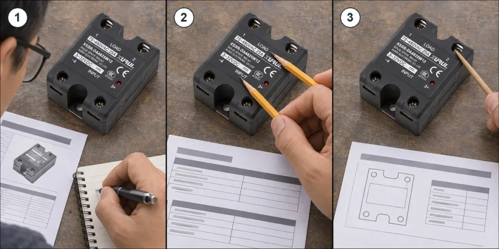
Step1: Verify the Complete Model Number
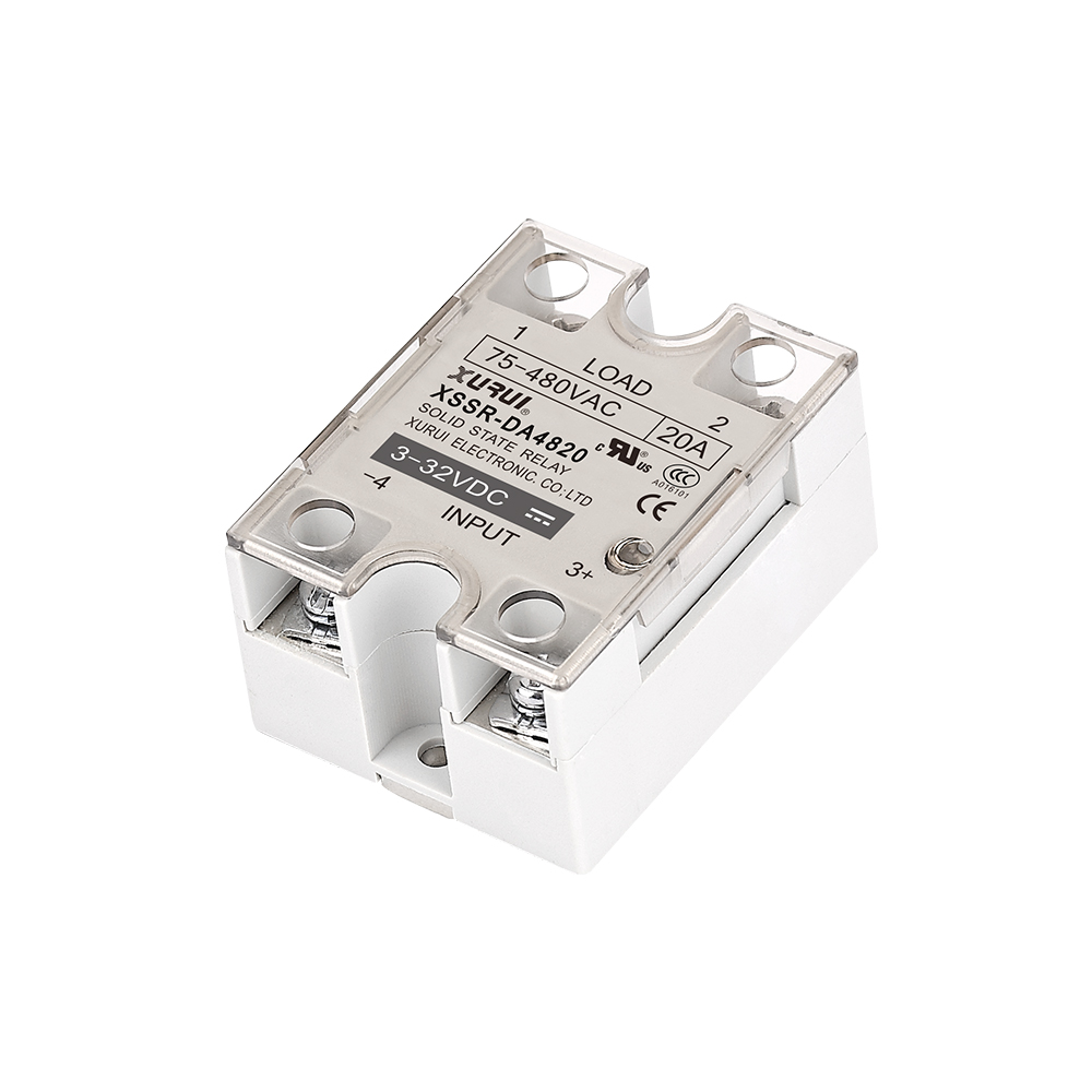
Record the full part number, including the input, output, and mounting suffixes. Use documentation that explicitly covers that code. One series can contain several configurations. The XSSR-W12 horizontal SSR series, for example, lists AC/DC control options and requires model-specific input and output verification. If the housing marking is incomplete, identify the device before proceeding. Case shape and a printed current rating are insufficient.
Step2: Confirm the Input and Load Ratings
Compare the controller’s output with the SSR’s input requirements. Verify the supply type, operating voltage range, required current, and any input polarity. For AC control, also check the permitted frequency.
Next, compare the load circuit with the output ratings. Confirm the supply type, voltage range, load current, and directional connection requirements. Keep the two sides separate when reading labels. A 12V control input can command an SSR switching a different load voltage; the relay does not supply 12V to that load.
Step3: Map the Diagram to the Physical Terminals
Use terminal identifiers and the drawing’s stated viewing direction to locate each connection. Check whether it shows a top, bottom, or terminal-side view. A PCB package viewed from underneath can appear reversed compared with the view from above.
Match each connection:
- Controller signal and return to the designated input terminals.
- Load supply and load to the designated output path.
- Positive and negative markings wherever the model specifies them.
For example, the OMRON G3NA-210B-UTU DC5-24 uses a rated 5–24 VDC input to switch a rated 24–240 VAC load. Its top-view diagram identifies terminal 3 as input positive, 4 as return, and terminals 1 and 2 as the AC switching path. Do not transfer those numbers to another SSR. If the schematic and device documentation disagree, resolve the model, drawing revision, and viewing direction before applying power.
Send XURUI the complete model number, control signal, load voltage, and load current to review compatibility before wiring.
Frequently Asked Questions
How Does an SSR Symbol Differ From an Optocoupler Symbol?
An SSR symbol shows a load-switching function, while an optocoupler symbol shows optical signal transfer, though the drawings can overlap. A basic phototransistor optocoupler shows an LED facing a light-sensitive transistor. An SSR drawing may include drive circuitry and an output switching stage. MOSFET-output photorelays are themselves a type of optocoupler, so appearance alone does not create a strict boundary between the categories.
Can a Solid State Relay Have a Normally Closed Output?
Yes, some semiconductor relays have normally closed outputs, commonly identified as Form B. A Form B photorelay conducts without input drive and switches off when the specified drive is applied. Form A describes normally open operation. These terms describe the output’s control state, independently of whether it switches AC or DC.
Where Can You Find SSR Symbols for CAD Software?
SSR symbols are available in CAD libraries and manufacturer-provided component resources. KiCad’s Relay_SolidState library includes several semiconductor relay types. Choose a symbol that matches the device documentation and works with the intended software. PNG and SVG images can illustrate a relay, but they lack the electrical pin definitions of an editable CAD component.
External Sources
- OMRON — Overview of Solid-State Relays and MOSFET Relay Operation
- OMRON — SSR Internal Circuit Configurations and Zero-Cross Function
- OMRON — Can a DC Load Be Used With an AC-Load SSR?
- Toshiba — Differences Between Photocouplers and Photorelays
- Toshiba — Form A and Form B Photorelay Contacts
- KiCad — Relay_SolidState Symbol Library