

A limit switch symbol shows how a mechanically operated contact changes state, but the symbol alone cannot identify a replacement switch. Buyers must read the symbol in its reference position, trace the related control circuit, and then collect the electrical and mechanical details that the schematic leaves out.
To specify the correct part, read the contact state, relate the symbol to machine movement, and add the electrical and mechanical data that the schematic omits. This process helps prevent reversed contact logic, incorrect terminal assignments, and switches that match the schematic but fail at the mounting point.
What Does a Limit Switch Symbol Show?
A limit switch symbol shows the relationship between mechanical movement and electrical contact state. It may also identify the device and direct the reader to other contacts, wiring locations, or drawing pages. It does not define the complete product.
Mechanical Actuation Marks
Mechanical actuation marks show that physical movement operates the contact. Depending on the drawing convention, the mark may suggest a plunger, roller lever, cam, or key. A linkage line may connect the actuator and contact, while a simplified schematic may show only the contact beside a limit switch tag.
The mark identifies a function, not physical dimensions. A roller symbol does not provide roller diameter, lever length, operating angle, allowed approach direction, or overtravel. Those details must come from the dimensional drawing and datasheet.
Contact State in the Unactuated Position
A control schematic normally shows a limit switch in its unactuated reference position unless the drawing notes or legend state otherwise. A normally open contact has no electrical continuity in that position. A normally closed contact has continuity and opens when the actuator moves far enough to operate the mechanism.
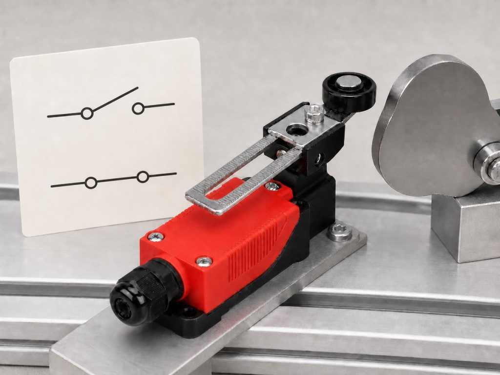
“Normal” describes the switch condition used to draw the contact, not necessarily the machine’s usual production condition. A machine cam may hold the switch actuated during normal operation. Buyers should confirm the physical reference position before using an NO or NC label from the drawing. The NO vs NC limit switch guide covers the effect of each contact state on control logic.
Device Tags and Cross References
Tags such as LS1, LS2, or a project-specific code identify the device across the drawing set. The same tag may appear beside the actuator on a mechanical layout, beside a contact in a ladder diagram, and beside a terminal in a wiring schedule.
Cross references point to the sheet, grid, rung, or terminal where related information appears. Follow every reference before deciding that the drawing shows one contact only. A physical switch can contain more than one contact, and the schematic may place each contact in a different part of the control circuit.
How Do Common Limit Switch Contact Symbols Differ?
Common symbols distinguish normally open, normally closed, and changeover contact functions. The drawing shows circuit logic, not the terminal layout or the contact rating of the physical switch.
Normally Open Contacts
A normally open contact shows a gap in the unactuated position. Mechanical actuation closes the path and allows the control signal to pass. This function often suits position confirmation, counting, or sequence initiation when the controller needs a signal only after the target reaches the operating point.
Because the symbol does not give voltage, current, load type, or wetting-current requirements, the control design must define them. The design must also state how the circuit responds to a wire break.
Normally Closed Contacts
A normally closed contact shows a complete path in the unactuated position, then opens when operated. NC contacts are often used in energized monitoring loops because a broken wire can also remove the signal. That behavior may help reveal a wiring fault, but it does not make the complete circuit safe. When the machine design requires forced mechanical separation, specify positive opening construction and require proof for the exact model.
Changeover and Mechanically Linked Contacts
A changeover contact transfers one common terminal between an NC path and an NO path. Depending on the documentation system, the drawing may call this SPDT, Form C, or one changeover contact. Buyers should state the required function instead of relying on one label.
Mechanical linkage means two or more contacts operate from the same actuator. The contacts may appear next to each other or on separate drawing pages. Linkage alone does not define contact timing, break-before-make behavior, direct opening, or terminal arrangement. The supplier drawing must state any of those details that the circuit needs.
How Do Engineers Read Limit Switch Symbols in Control Diagrams?
Engineers read a limit switch symbol as one part of a complete signal path. They trace the circuit, define what machine movement operates the switch, and record the required state before and after that movement.
Tracing the Control Signal
Start at the control supply or PLC input reference and follow the conductor through the limit switch contact to the coil, input, relay, or controller function it affects. Record wire numbers, terminal numbers, device tags, and cross references along the path. Do not assume that the page orientation shows current flow because drawing layouts vary.
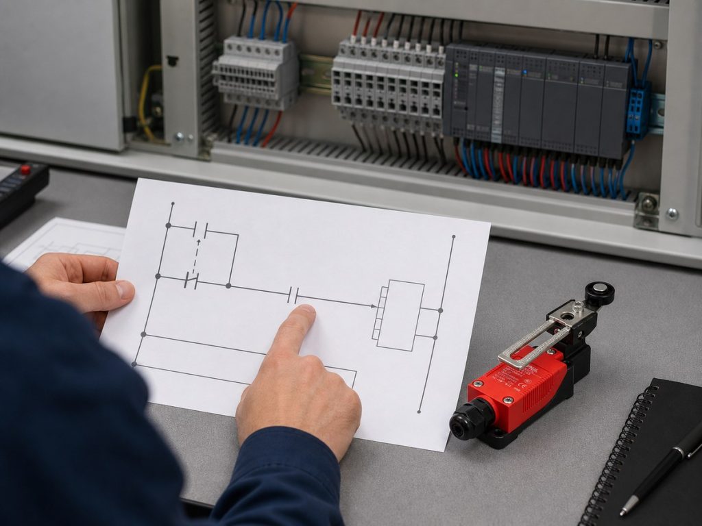
Check parallel branches and contacts with the same device tag before assigning the function. One overlooked bypass path can change the result. A contact that appears to stop a coil may only provide status feedback while another contact performs the stop function.
Relating Contact Changes to Machine Movement
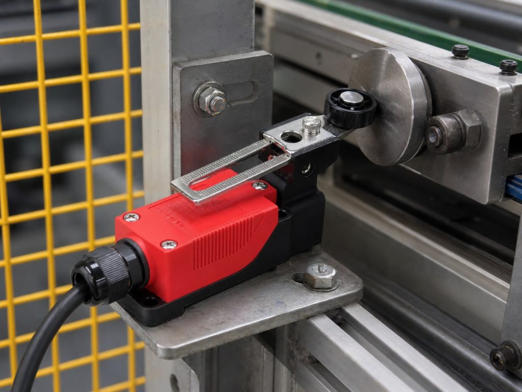
Identify the moving part, its direction, and the point where the actuator first operates. Then write the contact state before actuation, at the operating point, through overtravel, and after release. The travel limit switch guide explains how actuator movement, operating position, and machine travel work together.
A simple state record removes ambiguity:
| Machine condition | Actuator condition | Required contact state | Controller response |
|---|---|---|---|
| Before target reaches switch | Unactuated | Open or closed as designed | Continue, wait, or monitor |
| Target reaches operating point | Actuated | Changes state | Stop, reverse, count, or confirm |
| Target moves away | Released | Returns or remains latched | Reset, restart, or hold fault |
Defining the Required Switching Function
State the job in control terms before choosing a part. The switch may stop overtravel, confirm a guard position, signal an index point, or change a sequence step. Each job has a required input state, response to actuation, and response to faults such as a broken conductor.
Keep status feedback separate from a safety function. A contact that reports position to a standard PLC may not meet the architecture, monitoring, or positive opening requirements of a safety circuit. The approved machine risk assessment and control design must define that requirement.
How Should Buyers Convert the Required Function Into a Limit Switch Specification?
Buyers must add contact logic, electrical load, actuator motion, mounting, environmental limits, and verification documents before issuing an RFQ. The Xurui limit switch product range groups eight XZ-series pages, but final selection still depends on model-specific ratings and drawings.
Identifying Specifications Missing From the Diagram
List every item the drawing does not state. A useful RFQ or replacement check should cover the following fields:
| Specification area | Information to request |
|---|---|
| Contact function | NO, NC, changeover, number of contacts, mechanical linkage, positive opening if required |
| Electrical duty | Control voltage, current, AC or DC, resistive or inductive load, inrush, PLC input characteristics |
| Mechanical operation | Actuator type, approach direction, operating point, release point, overtravel, operating speed |
| Installation | Mounting footprint, body size, cable entry, terminal type, wiring space |
| Environment | Temperature, dust, water, oil, coolant, vibration, shock, corrosion exposure |
| Documentation | Terminal diagram, dimensional drawing, rating table, approvals, test records, drawing revision |
Do not copy a missing value from a similar switch. Mark the item “Not verified” until the supplier provides model-specific evidence.
Matching the Contact Arrangement and Electrical Load
Match the required function to the exact contact arrangement, such as 1NO, 1NC, 1NO plus 1NC, or one changeover contact. Confirm whether the contacts operate together and whether the diagram requires electrically separate circuits. A contact label does not prove isolation between circuits.
Rate the switch for the actual load conditions. Nominal voltage and current are not enough because PLC inputs may need reliable low-current switching, while contactor coils and solenoids can create inrush and inductive stress.
The Xurui XZ-8 (10A) limit switch has a verified 10 A version and double-break 1NO+1NC contacts. Xurui also lists a separate XZ-8 5A version, so the XZ-8 series name alone does not settle the contact rating.
Matching the Actuator, Mounting, and Environment
Choose the actuator from the target path. A plunger needs controlled straight movement. A roller lever can accept a moving cam, but the cam direction, lever angle, operating travel, and release travel must stay within the product drawing. The machine should reach its hard stop after the switch operates, not through the switch body.
Confirm the mounting hole pattern, actuator height, cable exit, service clearance, and bracket stiffness. Then match the exact model to dust, water, oil, coolant, temperature, vibration, shock, and corrosion exposure. Housing material or body shape does not prove an ingress rating.
Confirming Supplier Drawings, Datasheets, and Samples
Require a supplier package for the full part number, including suffixes. It should show the contact diagram, terminal view, dimensions, actuator data, electrical ratings, environmental limits, and approval scope. Compare its revision with the project drawing and bill of materials.
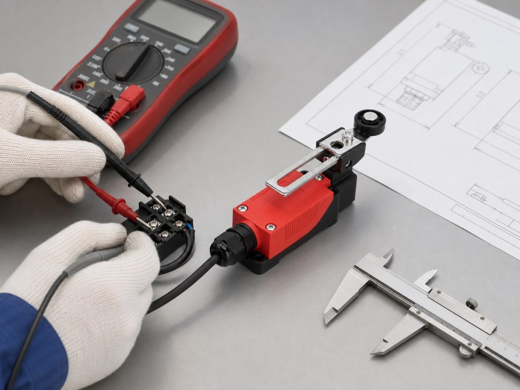
For replacement or volume sourcing, approve a sample before releasing the order. With power isolated, verify terminal continuity in the unactuated and actuated positions. Then mount the sample and confirm the real trip point, return action, controller input, and clearance through the machine cycle. The limit switch testing guide provides a practical test sequence.
When the available documents do not settle a match, Xurui Switch can review the schematic excerpt, load details, actuator path, mounting dimensions, environment, quantity, and required approvals. The final selection should remain tied to the confirmed part number and supplier documentation.
FAQs
Are Limit Switch Symbols the Same in IEC and ANSI Diagrams?
No. IEC and ANSI drawings can express the same NO, NC, or changeover function with different symbol geometry, tag conventions, and reference methods. Use the drawing legend and named project standard as the controlling source, then confirm the intended contact state from the circuit operation.
How Should Buyers Handle an Unlabeled or Outdated Control Diagram?
Do not select a replacement from an unlabeled or outdated diagram alone. Find the latest approved revision, record the installed part number and wiring, and have qualified personnel verify the circuit with power isolated. Qualified engineering staff should document and correct any difference before procurement issues a new specification.
Why Can One Physical Limit Switch Appear as Separate Contacts in a Schematic?
A schematic groups contacts by circuit function, so contacts from one physical limit switch may appear on different rungs or pages. The shared device tag and cross references connect those symbols to the same actuator. Buyers must count all related contacts before specifying the replacement.
What Should Buyers Do When Terminal Numbers Do Not Match the Datasheet?
Stop and resolve the mismatch before moving any wire. Check the full part number, contact-block suffix, drawing view, terminal-side orientation, and datasheet revision. If the markings still conflict, request a corrected supplier drawing and verify continuity with power isolated.
Can a Standard Limit Switch Replace a Positive Opening Limit Switch?
No, not when the safety design requires positive opening operation. A positive opening limit switch uses a verified mechanical path to force specified NC contacts open, while a standard spring-operated contact does not prove that function. Use only a model accepted by the machine’s safety design and validate the completed circuit before operation.
XURUI Engineering Team






