
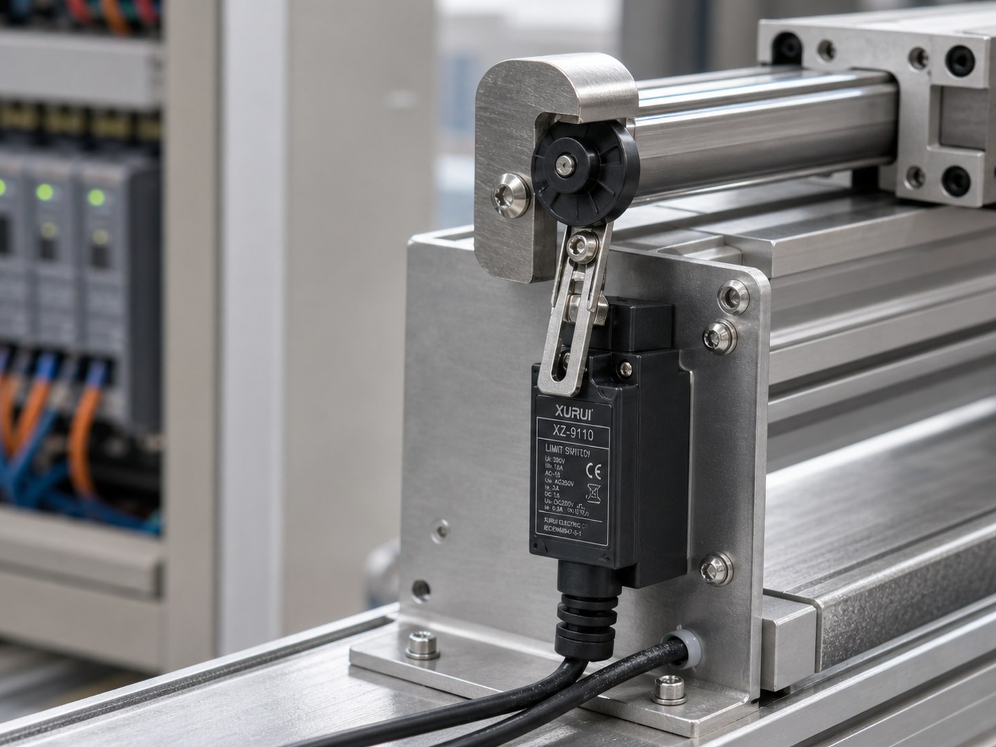
Use a travel limit switch to stop or confirm machine motion at a set end position before overtravel damages the actuator, motor, or frame. The switch gives the control circuit a physical position signal when a moving part reaches the end of travel.
This guide explains how a travel limit switch works, how NO and NC wiring change the signal, where the switch belongs, and how buyers should choose a limit switch for industrial motion.
What Is a Travel Limit Switch?
A travel limit switch is a mechanical limit switch or position switch that detects when a moving machine part reaches a set travel point. The switch is usually a standard limit switch used for a travel job, not a separate product category.
In a travel limit setup, a cam, carriage, door, hoist block, actuator, or machine arm presses the switch at the planned stop point. The switch changes contact state and sends a signal to a PLC, relay, drive, or control panel. That signal can stop motion, reverse motion, slow a drive, confirm a home position, or warn the controller that the travel path has gone too far.
Buyers asking this question need a physical end position signal when software position, motor timing, or operator judgment is not enough.
How Does a Travel Limit Switch Work?
A travel limit switch turns physical movement into an electrical contact change. The machine moves, the actuator touches the switch head, and the control circuit reads the changed contact state.
Actuator movement at the travel end
The limit switch actuator is the part that the machine touches. A plunger limit switch suits straight cams, a lever limit switch suits side movement, and a roller limit switch reduces drag when a cam slides across the head. The trip point should sit before the hard stop, leaving enough distance for the machine to slow while the switch actuator moves safely.
NO and NC contact change
The limit switch contacts change state when the actuator moves far enough. NO means normally open. The circuit stays open until the switch trips. NC means normally closed. The circuit stays closed until the switch trips.
For travel stops, NC wiring is common because a broken wire or loose terminal can open the circuit and create a fault signal. For position confirmation, NO wiring often works because the control only needs an arrival signal. Travel control usually starts with NO vs NC limit switch contact behavior because the chosen contact state changes how the controller reads faults and arrival signals.
Control response after the switch trips
The switch does not have to carry the motor load directly. In most industrial panels, the travel limit switch sends a low current signal to a PLC input, relay coil, contactor circuit, or drive input. Do not use a small switch contact as the main disconnect for a high current motor unless the switch rating and circuit design support that load.
What Problems Can a Travel Limit Switch Prevent?
A travel limit switch prevents the machine from treating the end of travel as a guess. The switch gives the control system a physical stop or confirmation signal when timing, load, or software position is not enough.
Overtravel and hard impact
Overtravel happens when a moving part passes the intended stop point. A travel limit switch trips before the hard stop, so the control circuit can cut, reverse, or slow motion before the machine hits the frame. This timing matters on hoists, gates, screw drives, transfer arms, and presses because motor inertia can carry motion past the commanded stop.
Missed home or end positions
Moving machines need a known end position before the next cycle starts. If a carriage does not fully return, the next command can start from the wrong place and push material, tooling, or a door into the wrong path. Broader position switch types include lever, plunger, roller, whisker, and spring rod heads, so the best choice depends on target shape and travel direction.
Motor strain and mechanical wear
A stalled motor keeps pushing after the mechanism has nowhere to go. That strain heats windings, loads gears, bends brackets, and wears couplings. A travel limit switch reduces that stress by telling the control circuit when the travel path has ended.
How Do You Wire a Travel Limit Switch?
Wire a travel limit switch based on the job the signal must perform. Stop circuits, position signals, and forward or reverse travel circuits use the same switch body in different ways.
NC wiring for stop signals
Use a normally closed limit switch when the signal must stop motion or reveal a broken circuit. In an NC travel stop circuit, the input stays active during normal travel and opens when the switch trips. This layout helps the controller catch a cut wire, loose terminal, or failed contact as a fault instead of reading silence as normal.
NO wiring for position signals
Use NO wiring when the controller only needs a positive arrival signal. In an NO circuit, the input changes when the switch trips at the end position. This setup fits simple position confirmation, counting, or indication, but NO wiring needs separate diagnostics when position loss creates risk.
Forward and reverse travel limit wiring
A moving axis often uses two travel limit switches: one at the forward end and one at the reverse end. Each switch tells the controller that the axis has reached one end of the allowed stroke. The control logic should block motion farther into the tripped direction while still allowing movement away from the limit.
Wiring checks before power-up
Check the contact form, terminal labels, and control voltage before power-up. Move the actuator by hand and confirm that the PLC input, relay, or drive input changes before hard contact and reacts in the intended direction. During commissioning, limit switch testing helps verify actuator travel, input response, and fault behavior before the machine runs under power.
Where Are Travel Limit Switches Used?
Travel limit switches fit machines that move along a known path and need a repeatable end signal. The exact switch head depends on the motion path, target shape, and contact force.
Cranes and hoists
Cranes and hoists use travel limit switches to stop trolley, bridge, hook, or lift motion at planned end points. An overhead crane limit switch or hoist limit switch supplies one travel signal inside a larger control system. In overhead crane systems, the signal usually works with braking, direction logic, and operator controls instead of acting alone.
Conveyors and transfer lines
Conveyors and transfer lines use travel limit switches to confirm pallet position, shuttle arrival, diverter movement, and pusher return. This signal reduces timing guesswork, so the PLC does not start the next step before a pusher, shuttle, or diverter reaches the correct position.
Gates, doors, and linear actuators
Gates, doors, and linear actuators use travel limit switches to confirm full open and full closed positions. A linear actuator limit switch can stop the motor at full extension or retraction and tell the controller which direction is still allowed. Leave enough clearance for full actuator travel, and lock the bracket so the trip point does not creep over time.
CNC machines, presses, and packaging equipment
CNC machines, presses, and packaging equipment use travel limit switches for axis ends, guard positions, material stops, and cycle confirmation. High vibration and oil exposure matter in these machines because a weak bracket, exposed contact block, or mismatched actuator can cause false trips, delayed trips, or damaged switch heads.
How Should Buyers Choose a Travel Limit Switch?
Choose a travel limit switch by matching the switch to the movement, load, environment, and control circuit. The right switch trips at the same point across repeated cycles without becoming the mechanical stop.
Actuator type and travel direction
Match the actuator to the direction of contact. Straight-line cams usually fit roller plungers or ball plungers. Side motion often fits roller levers. Soft or less exact targets may need spring rod or whisker heads. The switch head must move in the allowed direction, travel far enough to change contact state, and survive the contact force.
Electrical load and control voltage
Check whether the switch is feeding a PLC input, relay coil, contactor circuit, or small control load. Contact rating, AC or DC use, and terminal style must match the panel.
Xurui limit switches support AC and DC circuits, with rated load up to 10 A/250 VAC and 6 A/380 VAC by series. Confirm the exact series before quoting a rating.
Housing strength and vibration resistance
Pick the housing for the machine area. Metal housings fit exposed frames and harsh mounting points. Plastic housings can fit lighter enclosed equipment when impact risk is lower. Vibration can loosen brackets, so lock the fasteners and test the trip point after the machine runs under real load.
IP rating for dust, oil, or outdoor exposure
Dust, oil, coolant, and outdoor moisture can reach the actuator head and contact area. Use an IP-rated model when the switch sits near cutting fluid, washdown spray, or exposed machinery. For Xurui’s current limit switch range, XZ8 is the confirmed IP65-rated series. Other series need datasheet confirmation before an IP rating appears in customer copy.
Mounting clearance and false-trip risk
Leave enough clearance for the actuator to complete its rated movement without using the switch as the hard stop. False trips often come from loose brackets, long flexible arms, vibration, or a cam that brushes the actuator before the real end position. Correct the mechanical contact path before blaming the electrical circuit.
Reset behavior and repeat accuracy
The switch must release cleanly when the moving part leaves the end position. If the actuator sticks, drags, or releases late, the controller may hold the axis in a fault state. Repeat accuracy depends on the switch, bracket, cam shape, and machine backlash.
Which Xurui Limit Switches Fit Travel Limit Applications?
Xurui Switch builds industrial control switches for B2B equipment, including limit switches used on presses, conveyors, cranes, CNC lines, doors, and general machinery.
For travel limit applications, Xurui’s limit switch category lists eight XZ-series pages, with actuator options for roller plunger, ball plunger, adjustable roller lever, 4-way lever, spring rod, and whisker contact.
XZ8 for IP65-rated travel stop points
The XZ-8 10A Series Limit Switch fits travel stop points that need confirmed IP65 sealing, 10 A or 5 A versions, and double-break 1NO+1NC contacts. XZ8 also lists 1,000,000 mechanical operations, 100,000 electrical operations, 1500 VAC withstand, and 10 to 55 Hz vibration at 1.5 mm. Confirm the exact head type and contact rating before locking the part number.
XZ-9 metal housing for tougher mounting areas
The XZ-9 metal housing limit switch fits exposed travel stop points where the switch body may face knocks from brackets, frames, or moving workpieces. The die-cast metal housing gives the switch a tougher mounting base than a lighter enclosure. Match the actuator head to the cam direction, and confirm IP and contact ratings from the series datasheet.
XZ5, XZ7, XZ-93, and XZ-95 for standard travel limits
XZ5, XZ7, XZ-93, and XZ-95 cover standard travel limit jobs where the buyer needs a mechanical end position signal without a confirmed IP65 requirement from the brief. Across the Xurui limit switch category, safe category-level facts include -20 C to +60 C operation, 1,000,000+ mechanical operations, AC and DC support, 100 Mohm or more insulation at DC500V, and initial contact resistance of 25 mohm or less. Confirm series-level certificates and IP ratings before quotation.
FAQ
How far before the hard stop should a travel limit switch trip?
A travel limit switch should trip before the hard stop with enough distance for the motor, drive, or brake to stop the motion. The exact distance depends on speed, load, coast distance, and actuator travel. Test the trip point under real load instead of setting the switch by hand position alone.
Does a travel limit switch still need a mechanical stop?
A travel limit switch should not be the only physical boundary in most moving machines. The switch gives the control circuit a stop or position signal, while the mechanical stop protects the machine if wiring, logic, braking, or the switch fails. The stop should catch faults, not normal motion.
What is the difference between a travel limit switch and a home switch?
A travel limit switch marks the allowed end of motion, while a home switch gives the controller a reference point for position. One switch can sometimes do both jobs, but the machine logic must define that role. A home switch is about position reference, not only overtravel control.
Why does a travel limit switch trip before the machine reaches the travel end?
A travel limit switch may trip early because the cam is too long, the bracket has shifted, vibration touches the actuator, or the installer placed the switch head too close to the moving part. Check the mechanical contact path first. If the actuator is clean, then check wiring and controller logic.
When should buyers use a safety interlock switch instead of a travel limit switch?
Use a safety interlock switch instead of a travel limit switch when the device controls access to a guard, door, or hazardous machine area. Travel limit switches report machine position. Safety interlock switches handle guard and access control, with safety circuit behavior that standard travel switches may not provide.
XURUI Engineering Team






