
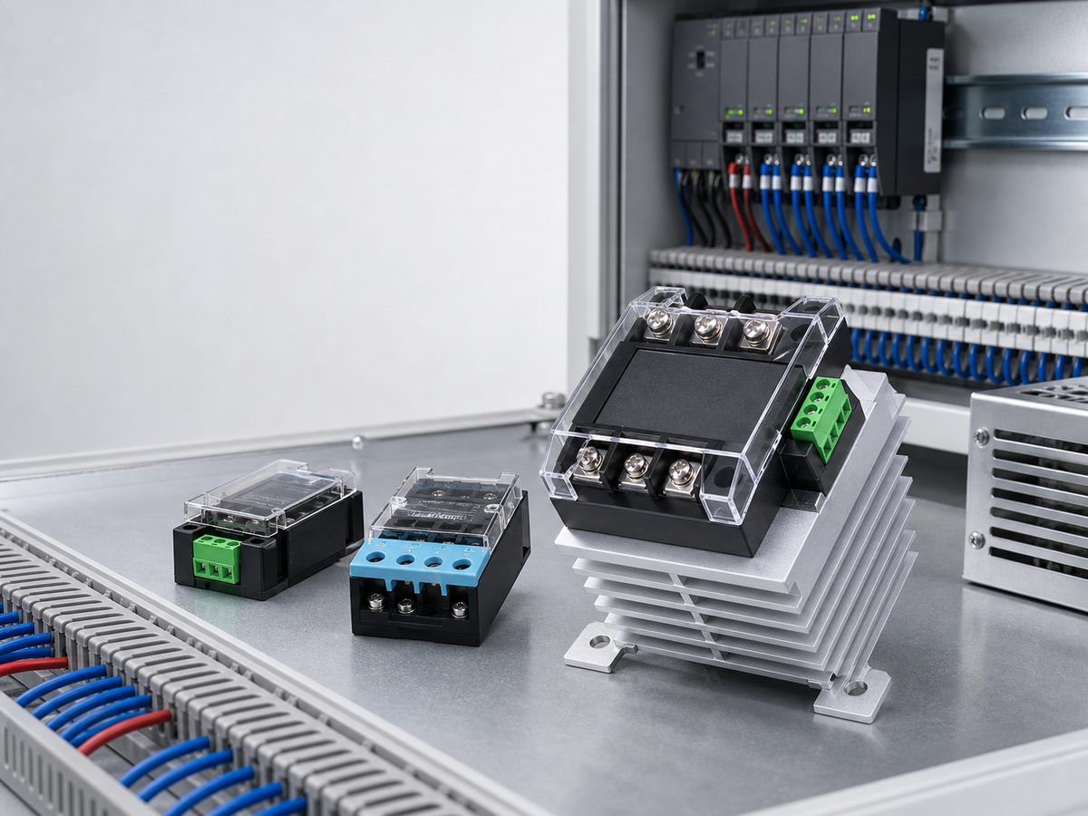
According to OMRON’s relay basics guide, relays fall into contact and contactless types. Mechanical and reed relays switch metal contacts. Solid state relays switch through electronics.
This guide compares mechanical, reed, and solid state relays for industrial control. It explains how each type works, where each one fits, and what buyers should check before matching a relay to a PLC output, sensor signal, heater, lamp, motor, or control panel load.
What Are the Main Types of Relays?
The main types of relays are mechanical relays, reed relays, and solid state relays. Each type uses an input signal to control another circuit. The difference is the switching method, which affects current rating, noise, speed, service life, heat, and failure risk.
Mechanical Relays
A mechanical relay uses a coil to move an armature and open or close contacts. The contact set may be normally open, normally closed, or changeover. This structure gives a physical contact gap, which suits simple logic, alarms, contactor coils, and interposing duty.
Reed Relays
A reed relay uses a magnetic field to operate reed contacts inside a glass tube. The sealed contact design fits low power signals, sensing circuits, and compact test points. A reed switch can also work as a reed relay element when the full assembly includes the right coil or package.
Solid State Relays
A solid state relay switches through semiconductor devices instead of moving contacts. An SSR can fit frequent switching because it has no mechanical contact wear. It also switches quietly, which helps in heater, lighting, and automation control.
How Do Mechanical, Reed, and Solid State Relays Work Differently?
Mechanical, reed, and solid state relays change the output state in different ways. Moving contacts raise wear questions. Reed contacts raise low current rating questions. Semiconductor outputs raise heat and leakage questions.
Mechanical Contact Switching
A mechanical relay starts with the coil. When the coil receives the correct voltage, a magnetic field pulls the armature and changes the contact state. When coil power drops out, a spring returns the contacts. This motion gives a dry contact, but it can also create bounce, arcing, or wear.
Reed Contact Switching
A reed contact sits inside a small glass tube. A magnet or coil field pulls the reeds together, so the circuit closes. The sealed tube protects the contact from outside air. That helps low power switching, but it does not make a reed device a high current relay.
Solid State Switching
A solid state relay uses an electronic input circuit and a semiconductor output device. The input side triggers the output side, often through optical or transformer isolation by series. For more detail, see How Does A Solid-State Relay Work. An SSR reduces mechanical wear, but buyers still need to allow for heat and match AC or DC output type.
How Do Relay Types Compare for Industrial Control?
Industrial control buyers should compare relay types by switching method, load behavior, cycle frequency, and failure risk. A relay that fits a low cycle circuit may not fit heater cycling, signal sensing, or safety monitoring.
Switching Method
Mechanical relays switch with moving contacts. Reed relays switch with small magnetic contacts inside a sealed tube. Solid state relays switch with electronic output devices. This first filter points buyers toward wear checks, low power load checks, or thermal checks.
Load Type and Current Range
Relay ratings depend on load type, not only current. A 2 A resistive load is not the same as a 2 A inductive load. Motors, solenoids, lamps, and heaters stress relay outputs in different ways.
Switching Frequency and Service Life
Switching frequency changes the relay choice. A mechanical relay may handle occasional switching well, but frequent cycling can wear the contact system. An SSR avoids mechanical contact wear, but it makes heat part of the design.
Failure Mode and Maintenance Risk
Mechanical relay failures often involve contacts that pit, stick, weld, or stop conducting cleanly. Reed devices can fail when the load exceeds the tube rating. SSR failures often point to heat, surge current, wrong output type, leakage current, or wiring errors. Safety circuits need safety-rated devices.
Relay Type Comparison Table
Use this table as a quick scan after the comparison points above.
| Factor | Mechanical relay | Reed relay | Solid state relay |
|---|---|---|---|
| Switching method | Moving contacts | Magnetic reed contacts | Semiconductor output |
| Best fit | General control circuits | Low power signals | Frequent load switching |
| Main risk | Contact wear | Overload damage | Heat and leakage current |
| Buyer check | Coil and contact rating | Contact rating and operate value | AC/DC output, current, heat sink |
The table is a starting point. The final choice still depends on the exact datasheet rating, load behavior, panel conditions, and safety function.
When Should Each Relay Type Be Used?
Relay choice should follow the job the circuit performs. One control panel can use different relay types because signal switching, load switching, and safety monitoring have different requirements.
General Control Circuits
Mechanical relays fit basic control circuits, interposing duty, alarms, pilot devices, and contactor coils when the circuit needs a simple contact output and the switching cycle is not extreme.
Low Power Signal Switching
Reed relays fit small signal paths, sensing circuits, and test points. Reed contacts are small, so the operate value, contact form, tube size, and load rating must come from the datasheet.
Frequent Load Switching
Solid state relays fit loads that switch often, such as heaters, lamps, and automation outputs. They remove mechanical contact bounce and contact wear from the switching point, which is why buyers often compare solid state relay vs mechanical relay for high-cycle loads.
Safety-Related Control Circuits
Safety-related circuits need devices chosen for the safety function. Emergency stops, guard doors, light curtains, and safety interlocks often use safety relays or safety controllers, not general relay outputs.
How Should Buyers Choose the Right Relay Type?
A good relay choice starts with the input signal and load. Then buyers should check switching frequency, heat, mounting, safety limits, and datasheet ratings.
Match the Control Input
Start with the control source. A PLC output, sensor, timer, temperature controller, or manual switch can all drive a relay input, but they do not provide the same voltage or current. If the input rating does not match, the relay may fail to operate, chatter, or overheat.
Match the Load Side
The load side must match voltage type, current, surge current, and load behavior. For mechanical relays, check contact voltage, contact current, contact form, and load category. For SSRs, check output type, rated current, surge current, leakage current, and whether the solid state relay works with DC.
Check Switching Frequency and Service Life
Low cycle control may not need an SSR. A mechanical relay can fit when the load is modest and switching is occasional. High cycle control changes the choice because mechanical contacts can wear faster.
Review Installation and Safety Limits
Panel layout matters. A relay may need socket space, DIN rail space, screw terminals, airflow, a heat sink, or a clear label area. If the relay is part of an emergency stop, guard door, or other safety function, check the safety circuit before choosing a general relay.
Where Does a Solid State Relay Fit in the Relay Family?
A solid state relay fits the relay family when the circuit needs electronic switching without moving contacts. SSR selection still depends on load type, current, heat, and wiring.
Strong SSR Use Cases
SSRs fit frequent switching, heater control, lighting control, and automated load control. Xurui’s Solid State Relay category includes single-phase and three-phase SSR options, AC zero-cross or random types by series, and DIN rail mounted options in H and 3H series.
Required SSR Selection Checks
Check the control input, output type, load current, surge current, leakage current, mounting surface, and ambient temperature. Before finalizing the panel layout, confirm whether the solid state relay needs a heat sink under the real load current and cabinet temperature. Xurui SSRs use solid state switching with no moving contacts, but they still generate heat. They are not IP65 devices by default.
Better-Fit Alternatives
A mechanical relay may fit better for occasional switching and visible contact action. A reed relay may fit better for low power signals. Use a safety relay when the circuit handles safety monitoring.
FAQ
Is a Reed Relay the Same as a Reed Switch?
A reed relay is not the same as a reed switch. A reed switch is the sealed contact element inside a glass tube. A reed relay adds a coil or package that lets an electrical input operate the reed contacts. Xurui’s XGH Series Reed Switch is a reed switch, not a complete reed relay module.
Can a PLC Output Drive a Solid State Relay Directly?
A PLC output can drive a solid state relay directly when the PLC output rating matches the SSR input voltage and input current. If the load needs isolation, contact multiplication, or more current than the PLC output can handle, use an interposing relay or interface module.
Why Can a Solid State Relay Stay Slightly On After It Is Turned Off?
A solid state relay can appear slightly on because SSR outputs can have off-state leakage current. This small current may make a light load glow or keep a sensitive input from dropping fully. Use the datasheet leakage value and load behavior to decide whether the circuit needs a bleeder resistor or another change.
Does a Solid State Relay Need a Heat Sink for Heater Control?
A solid state relay often needs a heat sink for heater control because current flow creates heat inside the output device. The need depends on load current, SSR rating, mounting surface, airflow, and ambient temperature. Check the SSR datasheet before assuming panel mounting alone is enough.
Why Does Load Type Change the Relay Rating?
Load type changes relay rating because each load stresses the output differently. A resistive heater is easier to switch than an inductive coil or motor. Lamps and capacitive loads can also draw high inrush current. Use the load category and surge behavior, not only the steady current.
What Is the Difference Between a Relay Coil Rating and a Contact Rating?
A relay coil rating describes the input side that operates the relay. A contact rating describes the output side that switches the load. A 24 VDC coil does not mean the contacts can switch any 24 VDC load. Buyers must check both ratings before using a relay in a control circuit.
XURUI Engineering Team






