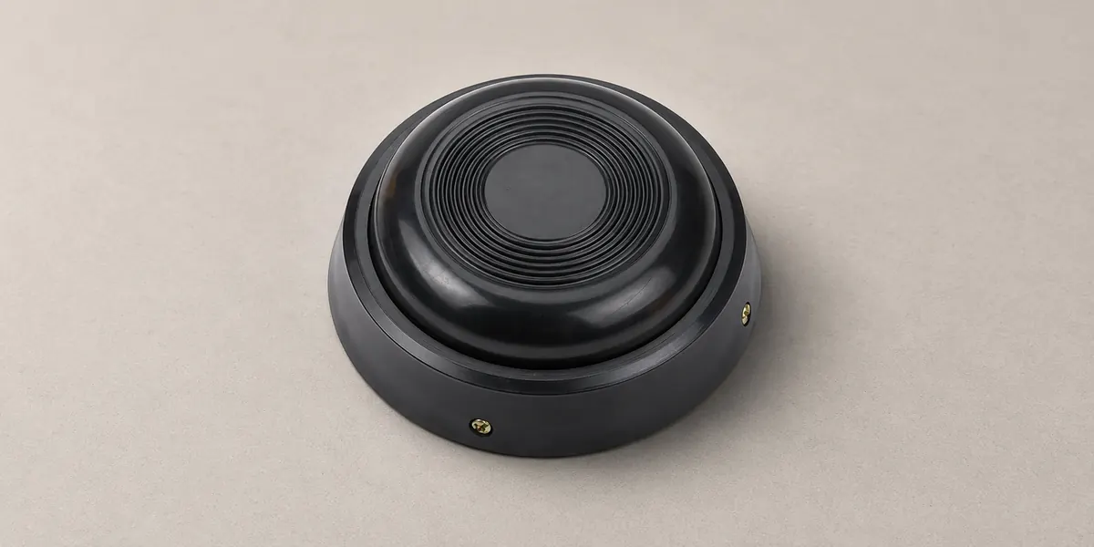
A medical foot switch must deliver the intended command, withstand its environment and behave predictably when something fails. A waterproof housing addresses only part of that job. For equipment manufacturers, selection starts with the control function and exposure conditions, followed by the evidence needed to support the finished device.
What Is a Medical Foot Switch?
A medical foot switch lets an operator control equipment with a foot while keeping both hands available. It may trigger an image, command a treatment table or regulate an instrument.
In medical equipment controls, the pedal may provide a simple electrical contact or an electronic signal. The host equipment interprets that signal and performs the action. A momentary pedal returns after release; a maintained pedal retains its selected state. A momentary press can still start a programmed cycle that continues after release, so pedal action and equipment behavior must be specified separately.
Which IPX Rating Does a Medical Foot Switch Need?
For cord-connected foot-operated controls evaluated under IEC 60601-1, Clause 15.4.7.3 sets an IPX1 minimum. Enclosures containing electrical circuits require at least IPX6 when intended for areas where liquids are likely at floor level, such as operating rooms. These are general-standard minima; standards for particular equipment can supplement or modify them.
For that wet-floor use, start with verified IPX6 protection. Add immersion protection when the intended exposure requires it. An IPX8 label alone does not establish compliance with the water-jet requirement.
Understand IPX Ratings and Their Test Limits
IEC 60529 defines ingress-protection tests. In IPX ratings, X means the solids-protection digit is unspecified. The rating applies to the tested assembly: complete switch sealing includes housing joints, actuator seals and cable entries.
| IPX Rating | Water Exposure Covered | What Buyers Should Verify |
| IPX1 | Vertically falling drops | Tested orientation and assembly |
| IPX4 | Splashing from any direction | Splash-test evidence |
| IPX6 | Powerful water jets | Jet-test evidence for the ordered configuration |
| IPX7 | Temporary immersion; 30-minute test | Depth, position and connector condition |
| IPX8 | Continuous immersion under specified conditions | Agreed conditions, more severe than IPX7 |
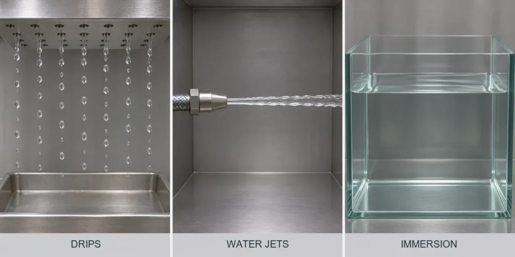
IPX7 and IPX8 do not automatically include IPX6. Where both jets and immersion matter, evidence must cover both. IPX8 conditions follow the relevant product standard or an agreement between manufacturer and user; the code does not supply one universal depth and duration.
Verify Compatibility With Cleaning and Disinfection Procedures
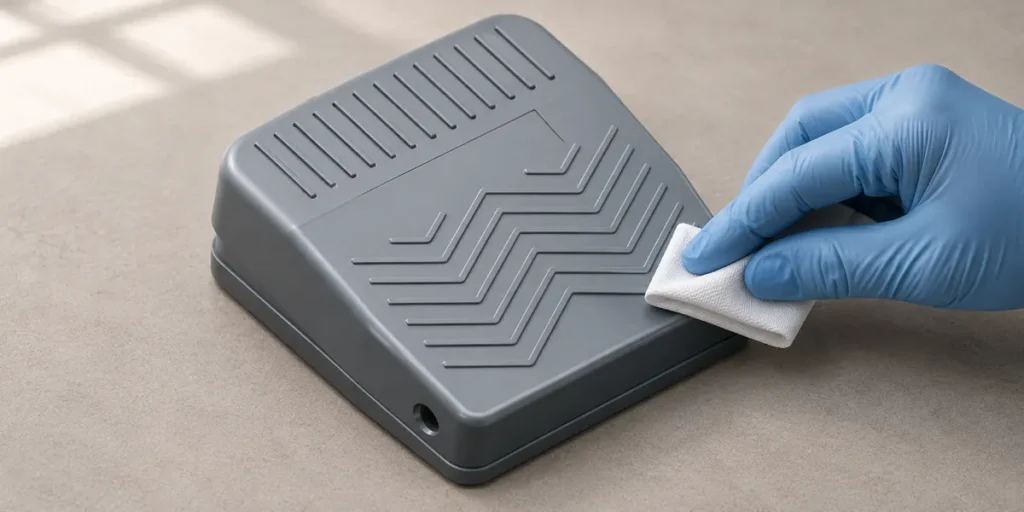
Water resistance does not establish resistance to cleaning chemicals, heat or repeated disinfection. Cleaning removes soil; disinfection reduces microorganisms. Sterilization is a separate process, and IPX8 does not establish suitability for steam sterilization.
The intended procedure must specify the agent, concentration, contact time, temperature and application method. Those conditions affect plastics, seals and markings differently. Repeated exposure can leave a pedal functional while degrading its enclosure protection. Validation therefore needs to address both effective cleaning and continued device performance. A floor control does not automatically require the same processing as an instrument that enters sterile tissue.
How to Evaluate Medical Foot Switch Safety
Safety depends on the complete command path, from the operator’s movement through the pedal and connection to the equipment’s response.
Verify Electrical and Interface Compatibility
The interface must match electrically and logically. Voltage, current and load type determine switching duty. Low-level electronic inputs also require suitable contact materials and minimum-load performance: some contacts need a minimum electrical load to switch reliably. A high power-current rating alone does not prove reliable signal switching.
Foot-switch contact symbols distinguish normally open contacts, which close when pressed, from normally closed contacts, which open. The connector pinout must preserve that intended behavior. Matching plug shapes cannot establish compatibility: an identical connector can carry different signals or put them on different pins.
Reduce Unintended Activation
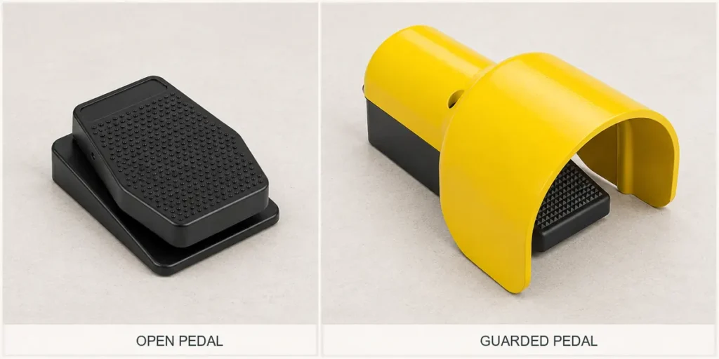
A protective hood can limit contact from stray objects, while a stable base helps keep the pedal in a predictable position. The choice among foot-switch guard configurations depends on whether the intended user can reach and release the correct control without obstructed movement.
Pedal spacing, operating force and tactile differences should be evaluated with representative users and footwear. Color can reinforce identification but should not be the only cue.
For cord-connected foot controls, IEC 60601-1, Clause 15.4.7.2, checks whether unintended control changes create unacceptable risk when the control is placed in abnormal positions on a flat surface. Clause 15.4.7.1 specifies a mechanical-strength test using 1,350 N for one minute over a circular area 30 mm in diameter, with the control in its normal use position. Any resulting damage must not create unacceptable risk.
Verify Fault Response
A fault can resemble a valid command. In a simple normally open contact circuit, a short across the signal wires can imitate a pressed pedal even after the operator lifts a foot.
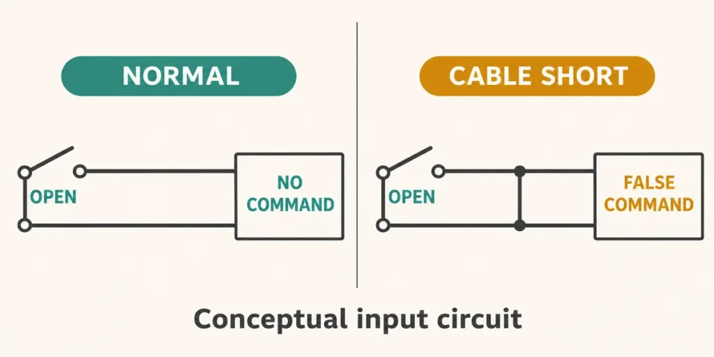
The system’s risk assessment determines whether it needs independent sensing channels, signal-consistency checks or communication monitoring. Additional channels can provide fault tolerance, but their safety contribution depends on channel independence, common-cause failures and how dangerous faults are detected or otherwise controlled. Tests should establish behavior during disconnection, stuck signals, power loss and reconnection. Where restarting could cause harm, restoring the connection must not silently resume operation.
Check Applicable Standards and Supporting Documentation
IEC 60601-1 addresses basic safety and essential performance. Basic safety concerns hazards such as electric shock. Essential performance concerns clinical functions whose loss or degradation would create unacceptable risk. Standards for particular equipment may add or modify requirements.
Useful evidence identifies the exact model, configuration, standard edition, tests and integration conditions. A certificate for an internal microswitch does not establish the safety of the pedal assembly or finished medical device. The equipment manufacturer must connect component evidence to system testing, including electrical protection, mechanical behavior and electromagnetic compatibility.
What Can Be Customized for an OEM Medical Foot Switch?
Original equipment manufacturer (OEM) options commonly concern pedal count, action, operating force, housing, guards, cables, connectors and markings. Electronic designs may also offer analog outputs or communication interfaces. Availability depends on the supplier and model.
Changes have engineering consequences. A new cable entry changes the sealing system; a different connector changes pin mapping and possibly shielding. Altering pedal force or spacing changes operation. Switching from contacts to an electronic sensor adds power and signal-processing requirements.
Existing test evidence remains useful only where it covers the revised construction. The efficient starting point is a documented platform that meets the main requirements, followed by an assessment of the proposed changes and the additional testing they require. The approved drawing, evaluation sample and production specification should describe the same configuration.
What to Include in an OEM Request for Quotation
A useful request for quotation (RFQ) describes the required behavior and acceptance criteria, rather than asking only for a “waterproof medical pedal.”
- State the equipment, operator task, target market and intended command.
- Provide electrical requirements, contact logic, connector drawings and pin assignments.
- Specify liquid exposure and the cleaning or disinfection procedure.
- Define pedal layout, force, travel, mounting space and guard requirements.
- Identify required evidence, sample tests and acceptance criteria.
- Include quantities, project milestones, traceability and change-notification expectations.
The resulting quotation should distinguish an available configuration from development work and identify which requirements need sample verification.
To review component suitability and configuration options with XURUI, submit your circuit and operating requirements.
Frequently Asked Questions
Can an Industrial Foot Switch Be Used in Medical Equipment?
Potentially, if its design and evidence support the medical device’s intended use. “Industrial” does not automatically disqualify a component, just as “medical” on a label does not qualify it. Selection depends on demonstrated performance within the finished equipment, including the required environmental protection and risk controls.
Is a Wireless Medical Foot Switch Better Than a Wired Model?
Neither is inherently better. Wireless control removes the signal cable and permits flexible positioning, but adds battery management, pairing and radio-link dependencies. FDA guidance identifies communication quality, wireless coexistence, security and electromagnetic compatibility as design considerations. Wired control avoids battery and radio-link dependencies, while retaining cable damage and routing risks.
When Should a Medical Foot Switch Be Replaced?
Replacement is appropriate when the pedal reaches the manufacturer’s replacement limit or cannot meet acceptance criteria through authorized servicing. Damaged insulation, cracked housings, deteriorated seals or unreliable return and switching warrant removal from service and assessment. Enclosure damage can let cleaning liquid reach internal components. A rated mechanical cycle life is not a universal replacement interval; actual loading, cleaning exposure and damage affect continued suitability.
External Sources
- IEC 60601-1, Edition 3.2: General Requirements for Basic Safety and Essential Performance
- IEC 60529, Edition 2.2: Degrees of Protection Provided by Enclosures
- FDA: Reprocessing Medical Devices in Health Care Settings
- FDA: Radio Frequency Wireless Technology in Medical Devices
- steute: User Interface With Integrated Sensors