
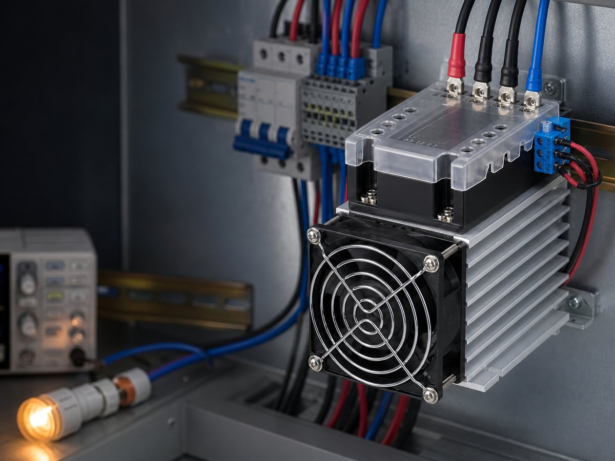
An AC solid state relay can pass a small off-state current because its semiconductor output and, on some designs, its internal suppression circuit do not create the air gap of an open mechanical contact. That current is usually normal leakage, but it can make a sensitive load glow, pulse, hum, or remain logically active.
The right response is to compare the exact SSR’s maximum leakage with the load’s real reset threshold, then test the circuit at the intended supply voltage. A live load that remains fully powered can also indicate re-triggering, wiring problems, or a failed-short output, so do not treat every symptom as normal leakage.
What Is Off-State Leakage Current in an AC Solid State Relay?
Off-state leakage current is the small current that passes from the AC supply to the load while the SSR input command is off. An AC SSR uses semiconductor output devices, commonly a triac or two antiparallel SCRs, rather than mechanical contacts. Those devices block most of the applied voltage when off, but their blocking state is not an infinite resistance.
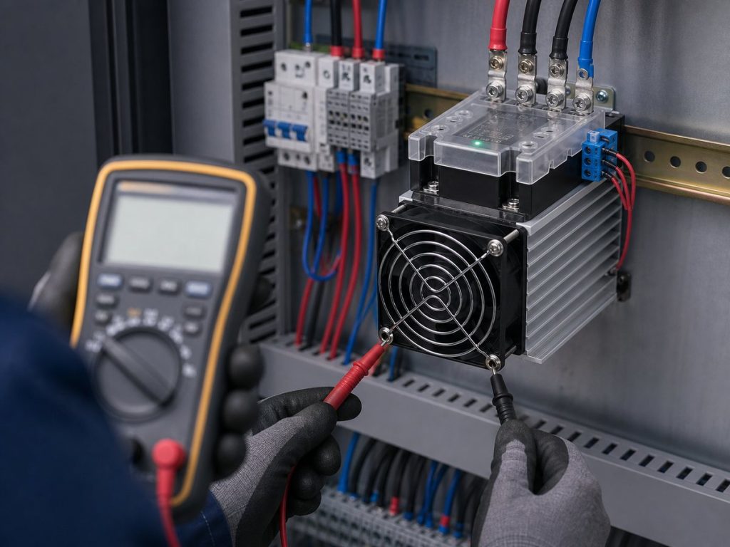
The leakage specification matters only with its test conditions. Read the maximum value, output-voltage condition, temperature condition, and whether an internal RC snubber is present. A high-impedance meter may show nearly the full line voltage at the load terminals even when the available current is too low to run a normal load.
What Creates Off-State Leakage and Apparent Turn-On?
Normal leakage and a true unintended turn-on can look similar at the load. The distinction matters because the correction for normal leakage is usually a load-side shunt, while a real re-triggering problem needs a circuit or SSR review.
Output-Device Blocking Leakage
The output device has a finite off-state leakage path. The current varies with the SSR design, the applied AC voltage, and temperature, so engineers must check an order code against its own datasheet instead of using a family-level value.
This behavior follows the basic operation of an AC solid state relay. A load with enough current demand will usually remain off, while a low-power electronic load may react to the same small current.
Leakage Through an Internal RC Snubber
Some AC SSRs include an RC snubber across the output to help control voltage transients. A capacitor passes AC current, so the snubber can add a reactive leakage path when the output device is off. Xurui documents RC suppression on some SSR series, not every SSR order code.
An LED driver or electronic input can charge through that path. The stored energy may produce a dim glow, an occasional flash, or a false input state even though the SSR has received no on command.
Unintended Re-Triggering at High dv/dt
A rapid output-voltage change can couple through the output structure and trigger an AC SSR that should be off. The result depends on the SSR’s specified off-state dv/dt immunity, wiring inductance, and the transient source. A short pulse that repeats with switching noise is different from steady leakage.
Check the exact SSR’s dv/dt rating and suppression arrangement before changing the circuit. Related dv/dt and di/dt SSR guidance helps separate voltage-transient concerns from load-current concerns.
Which Loads Can Misbehave Because of Off-State Leakage?
Loads with a low activation threshold, high input impedance, or an input capacitor are most likely to show a symptom. A resistive heater may ignore a leakage current that makes a compact electronic device visibly react.
| Load type | Common symptom when the SSR is off | What to verify |
|---|---|---|
| LED driver or indicator lamp | Dim glow, periodic flash, or incomplete shutoff | Input capacitor behavior and minimum operating current |
| Small AC coil or interface relay | Hum, weak pull-in, or uncertain release | Pick-up and drop-out behavior at the actual supply voltage |
| Electronic input with a capacitive front end | False input state or periodic transition | Input threshold, input impedance, and discharge path |
Low-Power LED Drivers and Indicator Lamps
Low-power LED drivers and indicator lamps can react to current far below the load current shown on the SSR nameplate. Their front-end capacitors may charge slowly, then release energy as a visible flash. A dim or flashing lamp does not by itself prove that the SSR has failed short.
Test the exact lamp or driver, including any parallel indicator wiring. Replacing one lamp type with another can change the symptom because the input circuit may be different even when both products use the same supply voltage.
Small AC Coils and Interface Relays
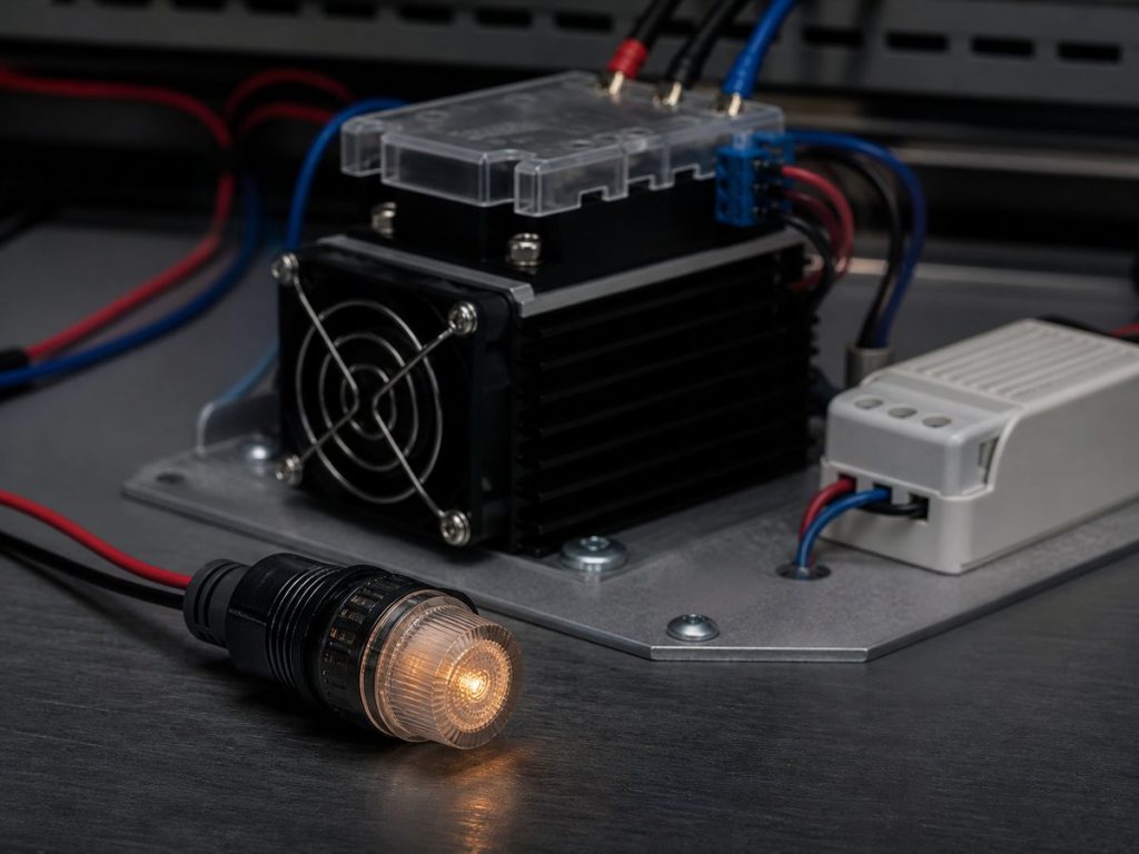
A small AC coil may not pull in fully, but leakage can still create hum, vibration, or a delayed release. Whether that happens depends on the coil’s impedance and its pick-up and drop-out characteristics, which are load specifications rather than SSR ratings.
Do not use a coil that is moving or buzzing as a maintenance isolation point. The coil circuit can remain energized enough to create an unexpected state even when the control signal is off.
Electronic Inputs With Capacitive Front Ends
Electronic inputs often draw little steady current and may include rectifiers and capacitors. Off-state leakage can raise the input voltage, charge the capacitor, and cross a logic threshold. A meter reading alone cannot show whether the input has enough current to change state.
Use the equipment maker’s input threshold and input-current data, then test the actual input with its production cable length and any shared-neutral or suppression wiring in place.
How Can Engineers Manage Leakage and Isolate the Circuit Safely?
Manage the symptom at the load, but keep maintenance isolation separate from normal control. An SSR output is an electronic switching path, so it should not be the only means used to make a circuit safe for work.
Comparing Maximum Leakage With the Load Reset or Activation Threshold
Start with the maximum off-state leakage in the exact SSR datasheet, not a typical value. Compare it with the load current or voltage at which the lamp extinguishes, the coil releases, or the electronic input resets. Repeat the test at the highest intended line voltage and the expected temperature range, because both the SSR and the load can change behavior.
For a new machine design, use the Solid State Relay Manufacturer category only to narrow the available SSR families. The final check still belongs to the exact order code, the exact load, and the real panel wiring.
Sizing and Validating a Parallel Bleeder Resistor or Module
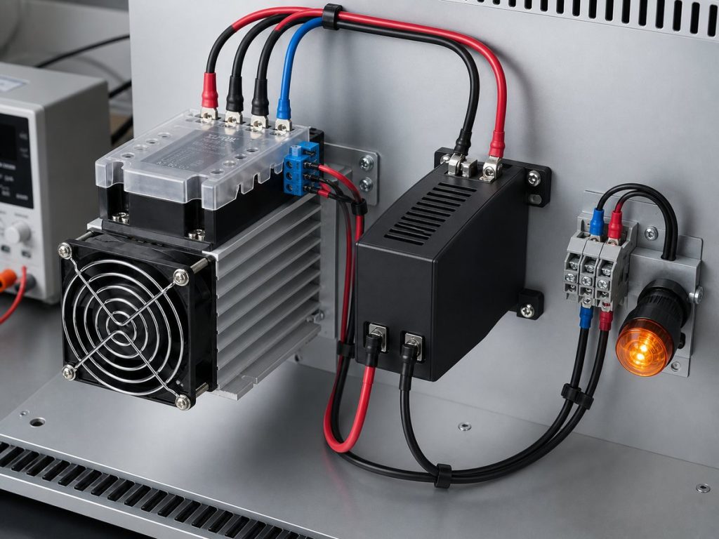
A parallel bleeder resistor or purpose-built module gives leakage current a lower-impedance path than the sensitive load. It is normally installed across the load or across the SSR output, subject to the equipment wiring design. The correct location and value depend on which voltage the load must see to remain reset.
When the SSR is off, a conservative first check is to keep the voltage across the sensitive load below its reset threshold. If the bleeder dominates the off-state path, use the SSR’s maximum leakage current to estimate that voltage. When the SSR is on, the same bleeder is continuously across the line, so its resistor power is approximately V squared divided by R. Select an AC-rated part or module with suitable continuous power, voltage, temperature, and enclosure capability, then validate temperature rise in the finished panel.
Checking the SSR Minimum Load Current Separately
Minimum load current is a separate selection check. Some AC SSR designs need enough load current to latch and hold correctly after an on command, especially near the AC current zero crossing. That requirement does not tell engineers whether off-state leakage will keep a sensitive load active.
Confirm both values: the SSR’s stated minimum load or holding-current condition, if specified, and the load’s reset or activation threshold. This prevents a design that solves a ghost-voltage symptom but still has unreliable on-state operation at a light load.
Using a Lockable Mechanical Disconnect for Maintenance
Use a suitable lockable mechanical disconnect upstream of the load circuit when maintenance requires isolation. Open the disconnect, apply the site’s lockout and tagout procedure, and verify absence of voltage with an appropriate test method before work begins. The circuit should not rely on an SSR’s off command as a maintenance boundary.
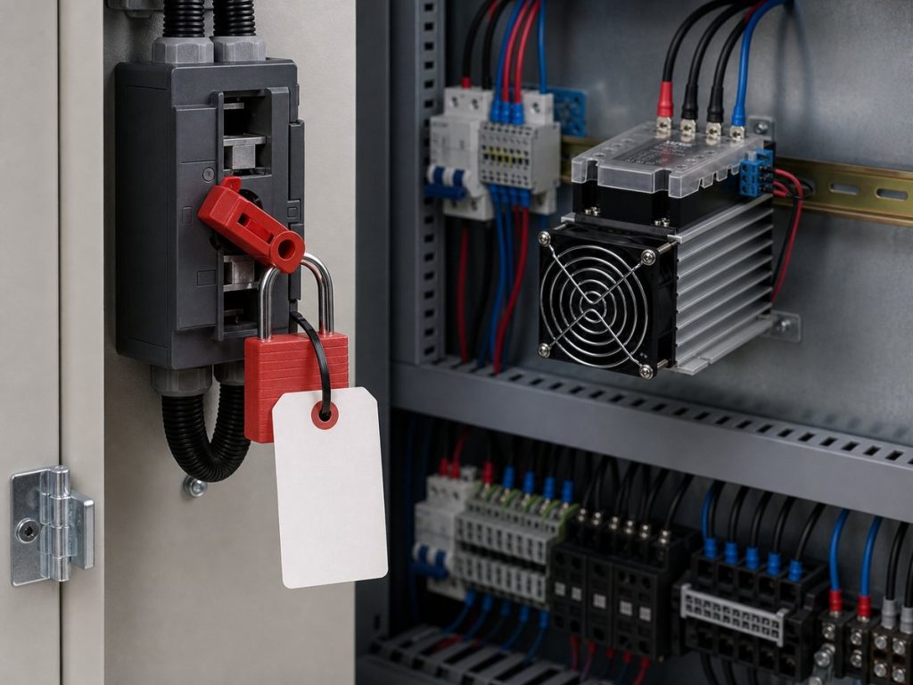
The same discipline belongs in the broader SSR wiring plan, along with correct overcurrent protection, grounding, terminal work, and first-power testing.
FAQs
How Can Engineers Distinguish Normal Leakage From a Failed-Short SSR?
Normal leakage stays within the exact SSR’s specified off-state limit and often produces a symptom only on a sensitive load. An SSR that has failed short can supply enough current to operate the normal load as if the relay were on. Measure the load current with the input command removed, test with a known suitable load where safe, and compare the result with the datasheet limits. A high-impedance voltage reading alone does not prove an output failure.
Can Residual Control-Side Voltage Keep an AC SSR On?
Yes. Residual voltage or current at the SSR input can keep the input circuit above its release threshold, which is a control-side problem rather than output leakage. Check the controller output type, off-state voltage and current, input polarity, shared wiring, and the exact SSR input release specification. Remove or isolate the command signal during a controlled test before blaming the output stage.
How Should an OEM Test Off-State Behavior With a Sensitive Load?
Test the actual load at the highest intended supply voltage, with the control input confirmed off and the final cable and suppression arrangement connected. Record load voltage, load current, and the load’s physical response, then repeat the test after adding the proposed bleeder. Use safe energized-work procedures and verify the measurement method, because a meter with high input impedance can show a misleading ghost voltage.
Which Datasheet Details Must Match the Exact SSR Order Code Before Approval?
Match the load-voltage range, rated and minimum load current where specified, control-input range, switching mode, maximum off-state leakage and its test conditions, off-state dv/dt immunity, protection components, and installation limits. Confirm the exact series and suffix because Xurui SSR families can differ in output range, input options, mounting format, and protection arrangement. For order-specific documents or technical confirmation, use Xurui Switch after engineers define the requirements.
Does Zero-Cross Switching Eliminate Off-State Leakage Current?
No. Zero-cross switching controls when an SSR turns on after it receives an on command, usually near the AC waveform’s zero-voltage point. Off-state leakage depends on the output device and any suppression components, so it remains a separate datasheet and load-compatibility check.
XURUI Engineering Team






