
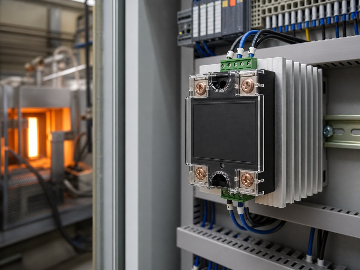
Use a zero-cross solid state relay for compatible AC resistance loads that switch on and off normally or through time-proportional control. Use a random turn-on solid state relay when the control system must start conduction without waiting for the next AC voltage zero crossing. Choose the mode from the load behavior and required timing, not from the SSR current rating alone.
Zero-cross and random turn-on describe how an AC SSR begins conduction after receiving an input command. They do not confirm AC or DC output compatibility, motor or transformer suitability, thermal capacity, or protection requirements. Those checks remain part of the SSR selection.
Which Turn-On Mode Fits the Load and Control Method?
Start with the load waveform and the timing the controller actually needs. A zero-cross SSR waits until the AC voltage is near a zero crossing. A random turn-on SSR can begin conduction without that wait. Both require confirmation of output voltage, running current, inrush current, heat dissipation, and the exact output rating.
| Load or Control Condition | Usual Direction | Reason | Additional Check |
|---|---|---|---|
| Resistance heater with ordinary on-off or time-proportional control | Zero-cross | Starting near zero voltage can reduce switching disturbance. | Cold resistance, inrush, SSR rating, heat sink, and cabinet temperature. |
| Load that needs a selected firing point within an AC cycle | Random turn-on capability | The output can respond without waiting for the next zero crossing. | Compatible controller, firing method, harmonics, RMS current, and thermal performance. |
| Motor, solenoid, or other inductive load | Load-specific review | Starting current and current lag can change the switching and turn-off behavior. | Load rating, surge capability, protection, and application data sheet. |
| Transformer primary or highly saturable inductive load | Specialized energization review | Trigger mode alone does not control magnetizing inrush. | Energization method, worst-case inrush, and approved switching device. |
| DC load | DC-output SSR selection | AC zero-cross and random turn-on labels do not describe DC interruption. | DC output topology, polarity where applicable, turn-off behavior, and stored load energy. |
The AC SSR switching path is useful background when reviewing the input command and output behavior together.
When Is a Zero-Cross SSR the Better Choice?
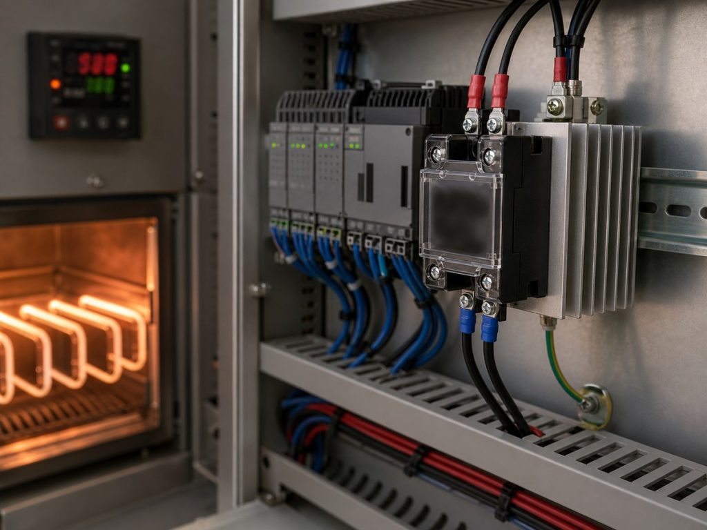
A zero-cross SSR is usually the practical choice for a compatible AC resistance heater that does not need a precise conduction start point inside each half-cycle. The SSR waits for a near-zero voltage point after the input turns on, then conducts for the commanded AC cycle or cycles.
Resistance Heating and Ordinary Switching
Temperature controllers often use on-off or time-proportional control for resistance heating. In that arrangement, zero-cross switching can reduce electrical disturbance compared with applying voltage at an arbitrary point on the sine wave. It is often the simpler approach for a slow thermal process.
Zero-cross selection does not remove startup current. A heater can have lower cold resistance, and a lamp can draw high cold-filament current. Size the SSR, fuse, protection components, and heat sink from the actual load profile rather than steady operating current alone.
Limits of Zero-Cross Switching
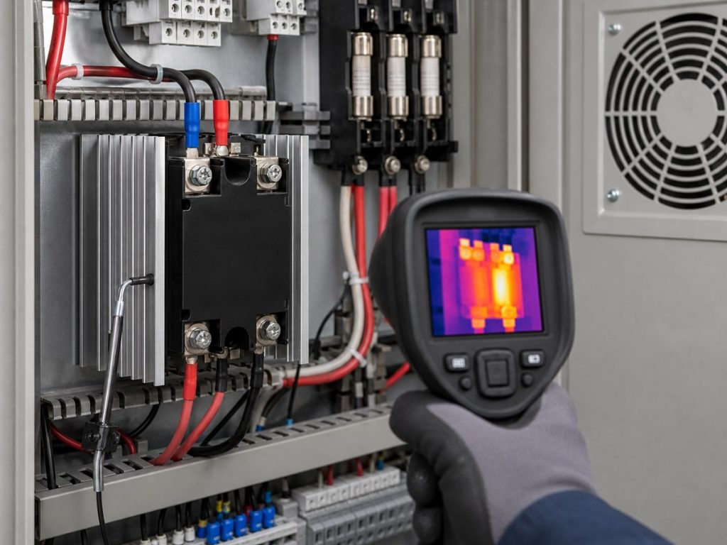
Zero-cross operation is not a general inrush cure. A transformer or strongly inductive load can still draw an unfavorable surge depending on its magnetic state and the applied voltage point. The output circuit also needs a protection design that fits its transient conditions.
An SSR is not a service disconnect or safety isolation device. Use the approved safety circuit and disconnecting means for maintenance and fault isolation.
When Does Random Turn-On Meet a Real Control Need?
Choose random turn-on when the control design needs conduction to begin without waiting for the next voltage zero crossing. If ordinary heater cycling already meets the process requirement, random turn-on adds complexity without creating a useful benefit.
Phase-Angle and Timing Control
Phase-angle control changes how much of each AC half-cycle reaches the load. A compatible controller sets the firing point, and the output device must accept that firing method. Random turn-on capability can be part of that system because the output can respond at the selected point in the waveform.
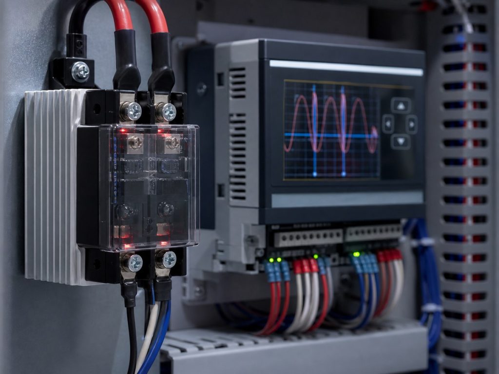
A random turn-on SSR does not create phase-angle control by itself. The design still needs a matched controller, a defined firing strategy, and a review of harmonics, RMS current, electromagnetic compatibility, and heat. Confirm the controller output range, drive current, timing, and off-state behavior with the AC, DC, and three-phase SSR wiring guide.
Which Loads Need Separate Inrush and Turn-Off Review?
Motors, solenoids, transformers, capacitive-input circuits, lamps, and mixed loads need more than a zero-cross versus random decision. High first-cycle or starting current can exceed the normal running condition, while inductance can shift current relative to voltage and affect semiconductor turn-off.
Motors and Solenoids
Do not treat a general-purpose resistance-load rating or a random turn-on label as proof that an SSR suits a motor or solenoid. Confirm the starting duty, locked-rotor or comparable inrush condition, required motor-control rating, protection, and SSR thermal limit. Some applications use random turn-on because of their inductive behavior, but the correct choice remains application-specific.
Review the SSR’s applicable transient limits with the dv/dt and di/dt guide before approving the circuit.
Transformer Primaries and Capacitive Inputs
For a transformer primary, neither ordinary zero-cross switching nor a generic random-turn-on SSR proves acceptable energization. The engineering review must address magnetizing inrush and whether the application needs a controlled voltage-application point or another specialized method.
Capacitive-input loads, such as LED drivers and switching power supplies, can create a high first-cycle inrush. Check the load’s input current profile against the SSR surge rating, transient limits, fuse coordination, and thermal arrangement.
What to Confirm Before Ordering an SSR?
Specify turn-on mode as one field in the electrical requirement. The order record should connect that mode to the exact AC load, control method, and tested operating conditions.
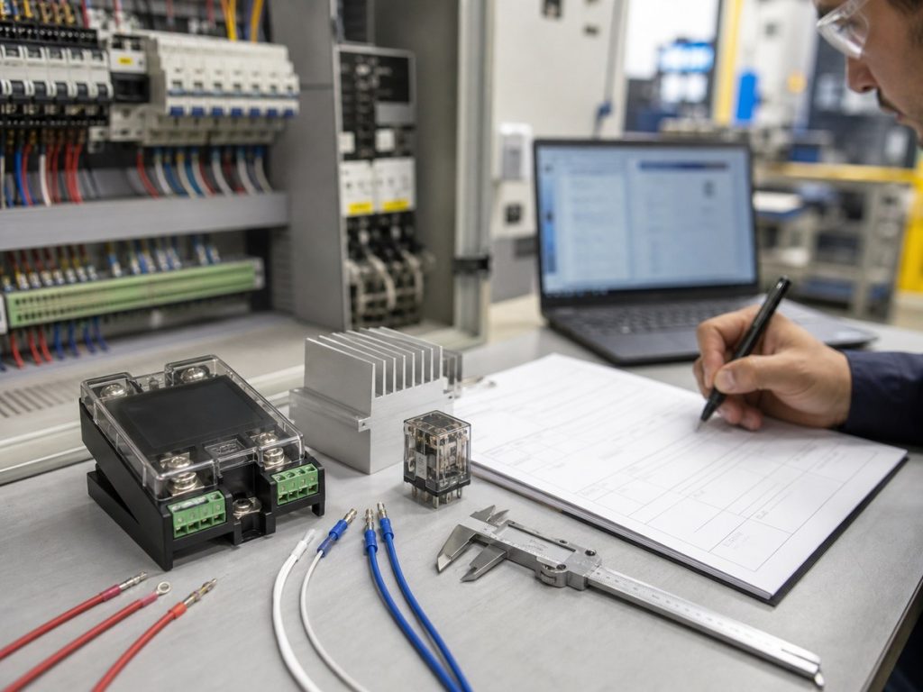
- Record output type, load voltage, frequency, phase, running current, and worst-case inrush current.
- Identify the load as resistance heating, motor, solenoid, transformer, lamp, capacitive input, or a mixed circuit.
- State the required trigger mode, controller output range, timing requirement, and any input polarity or drive-current limit.
- Confirm the exact SSR series and order code, output rating, surge and dv/dt limits, thermal derating, mounting method, heat sink, fuse, and suppression components.
The Xurui Solid State Relay category lists the available AC SSR families. Xurui Switch offers zero-cross and random-turn-on options by series, so use the exact data sheet and order code to confirm the proposed unit. For configuration review, provide the load details, controller output, cabinet conditions, and required switching behavior to Xurui Switch.
Frequently Asked Questions
How Much Turn-On Delay Should I Expect From a Zero-Cross SSR?
A zero-cross SSR can wait until the next AC voltage zero crossing after it receives the input command. The delay can approach half an AC cycle, which is about 10 ms at 50 Hz or 8.3 ms at 60 Hz. Confirm that delay against the machine sequence before selecting zero-cross switching for a timing-sensitive function.
Can a Zero-Cross SSR Dim a Lamp?
An ordinary zero-cross SSR is not the normal choice for phase-angle lamp dimming. It starts conduction near a voltage zero crossing rather than at an adjustable point within each half-cycle. Use a compatible dimming control method and output device, then separately check lamp inrush and the load rating.
Can I Use High-Frequency PWM to Drive a Random Turn-On SSR?
Random turn-on does not mean an AC SSR can chop the output at a high PWM frequency. Some AC semiconductor outputs continue conducting until load current falls low enough to turn off. Use a control method and power device designed for the required switching pattern, then confirm the input timing and output behavior in the data sheet.
Is Peak Switching the Same as Random Turn-On for a Transformer?
No. Random turn-on means the output can begin conduction without waiting for a zero crossing, while peak switching or controlled energization applies voltage at a planned waveform point to manage transformer inrush. Do not assume a generic random-turn-on SSR provides that behavior without confirmation from the device documentation and the control design.
Can a Zero-Cross SSR Switch an LED Driver or Switching Power Supply?
Possibly, but the trigger mode alone does not establish suitability. An LED driver or switching power supply can have a capacitive input that draws a high first-cycle inrush current. Confirm that load profile against the SSR surge rating, transient limits, fuse coordination, and thermal arrangement before release.
XURUI Engineering Team






