
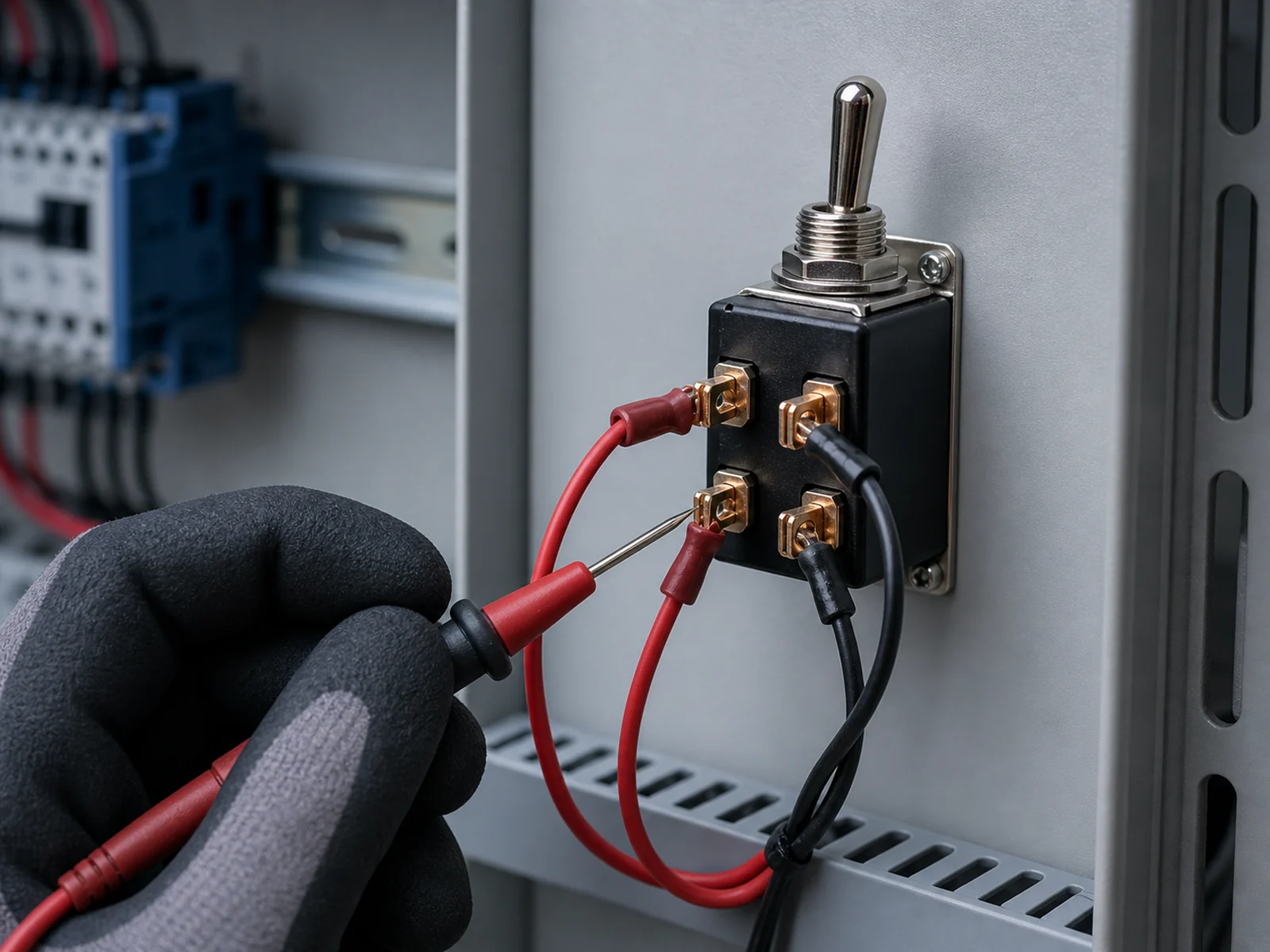
A DPST switch diagram shows two separate contact paths that open and close together through four terminals. Before wiring, match the manufacturer’s terminal view to the physical switch, then verify each pole with power isolated. A guessed terminal pattern can cross circuits or leave a conductor energized.
This guide explains how to read OFF and ON states, identify pole pairs, wire each path, and choose a DPST switch by load, action, mounting, and panel conditions.
What Does a DPST Switch Diagram Show?
A DPST switch diagram identifies the two terminals in each pole and shows whether both contact paths are open or closed in each switch position. The manufacturer’s drawing takes priority when a model uses normally closed contacts or different position labels.
Four Terminals and Two Poles
DPST means double pole, single throw. “Double pole” means one operator controls two circuits. “Single throw” means each pole makes or breaks one contact path instead of selecting between two outputs.
A typical DPST switch has four electrical terminals, two for each pole. Terminal 1 pairs with terminal 2, while terminal 3 pairs with terminal 4 in this example:
Typical normally open DPST contact state:
| Switch position | Pole 1, terminals 1 and 2 | Pole 2, terminals 3 and 4 | Circuit state |
|---|---|---|---|
| OFF | Open | Open | Both paths have no continuity |
| ON | Closed | Closed | Both paths have continuity |
The numbers above are examples, not a universal terminal layout. Printed terminal numbers and the model datasheet take priority. SPST, SPDT, DPST, and DPDT identify contact logic, not a standard physical terminal pattern.
Two Single-Throw Contact Paths
Each pole makes or breaks one path. Unlike a DPDT switch, a DPST switch does not route either pole between two outputs. Use DPST when two conductors or two control paths must turn on and off together. The contact diagram does not establish voltage, current, insulation, or approval ratings.
Mechanically Linked, Electrically Separate Poles
The two poles share one lever, rocker, or plunger, but they do not share an electrical path. One action controls both poles without joining the circuits. This mechanical link does not make a standard DPST switch a safety device or prove that it can separate unrelated voltage systems. Contact spacing, insulation ratings, applicable codes, and the manufacturer’s instructions still govern the permitted use.
How Do You Read a DPST Switch Diagram?
Read a DPST switch diagram by tracing each pole separately in every marked operator position. Identify the two terminal pairs first, then note whether each pair is open or closed. Do not infer connections from the physical shape of the switch.
Open Contact Paths in the OFF Position
In a common maintained ON/OFF DPST switch, the OFF symbol shows a gap in both paths. The gap means that neither terminal pair should have continuity. Trace the poles separately because an open path on Pole 1 does not identify the Pole 2 terminals. If the datasheet shows normally closed contacts or different position labels, follow that drawing.
Closed Contact Paths in the ON Position
In the ON position, each contact touches its paired terminal. With the switch disconnected, a continuity tester should confirm a closed path across both pairs. If only one pair closes, check the terminal map and operator position before treating the switch as damaged. Keep the circuit isolated until both results match the diagram.
Matching the Schematic to the Physical Terminals
Start with the terminal numbers or contact symbols molded into the body. Compare those markings with the manufacturer’s terminal view. A front view and a terminal-side view mirror each other, so confirm the drawing orientation before assigning wires.
Do not assume adjacent terminals form a pole. Some products place each pair in a row, while others use columns or a nonintuitive molded layout. The DPDT switch diagram applies the same rule to a six-terminal changeover layout: map each function from the contact drawing, not terminal position alone.
How Do You Wire a Four-Terminal DPST Switch?
Confirm the terminal pairs and isolate every energy source before wiring a four-terminal DPST switch. Each circuit passes through one pole. Only a qualified person should work on hazardous-voltage circuits under the approved equipment procedure and applicable electrical rules.
Checking the Manufacturer’s Terminal Diagram
Find the exact part number and terminal diagram before cutting or landing wires. Check the contact form, operator positions, view orientation, line and load markings, AC or DC rating, and load category. Verify the required protective device separately.
Do not copy a diagram from a switch that merely looks similar. A lighted four-terminal switch may include lamp connections. Another four-terminal mechanism may contain different internal links. The same model-first check applies when you wire a toggle switch in a control panel.
Identifying Pole Pairs With Power Isolated
Disconnect and lock out every energy source before testing continuity. Follow the worksite’s energy-control procedure, including any required tagout steps. A qualified person must use suitable test equipment to confirm the absence of voltage because a switch position or visual check cannot verify the circuit’s energy state.
With all conductors removed from the switch, use a continuity meter to map the contacts:
- Label the four terminals according to the manufacturer drawing.
- Test the first expected pair in OFF and ON.
- Repeat the test for the second expected pair.
- Confirm that no unintended continuity exists between the two poles.
- Record the verified pairs before connecting conductors.
Continuity testing identifies terminal pairs. It does not confirm load capacity.
Connecting Each Switched Path
Connect the two conductors from the first circuit across the paired terminals of Pole 1. Repeat the process on Pole 2. Follow the marked line and load sides when the manufacturer assigns them.
Do not bridge the poles unless the approved circuit drawing requires it. Wire color does not prove terminal function. The equipment design and applicable code determine conductor size, grounding, overcurrent protection, and which conductors the switch must open.
Inspecting the Wiring Before Energizing
Inspect and test the finished wiring before restoring power. Check:
- Correct terminal pairs and operator labels
- Terminal tightness and manufacturer-specified torque
- No loose strands, exposed copper, damaged insulation, or uninsulated jumpers
- Adequate spacing, wire support, strain relief, and rear-panel clearance
- Correct fuse or circuit breaker protection for the conductors and load
- Expected continuity in both switch positions, with no cross-pole connection
- Covers and guards installed before energizing
Remove test leads and temporary jumpers, warn affected personnel, and follow the approved reenergization procedure. Complete the required visual inspection and electrical checks before restoring power.
How Do You Choose the Right DPST Switch?
A suitable DPST switch must match the circuit’s contact form and electrical load. It must also fit the panel, wiring method, operating action, and environment. Four terminals alone do not establish suitability.
Required Pole and Throw Configuration
Use DPST when two paths must open or close together and neither path needs a second output. Choose SPST for one path, SPDT for one changeover path, or DPDT for two changeover paths. A normally open contact closes when operated, while a normally closed contact opens. XURUI’s XT Series Toggle Switch includes DPST options for panel designs. The exact part must still match the required contact state, ratings, and terminal layout.
Voltage, Current, and Load Type
Match the exact rating for voltage, current, AC or DC, and load type. One switch may carry different ratings for resistive, lamp, motor, and other inductive loads because inrush current and switching arcs change contact stress. The permitted current therefore depends on both voltage and load type.
Use the manufacturer rating for the expected operating and inrush conditions. Do not transfer an AC rating to a DC circuit or treat a headline current value as valid for every load. These toggle switch rating checks also help buyers compare pole count, throw count, and load suitability before choosing a part.
Maintained or Momentary Action
A maintained DPST switch stays in position after the operator releases it. A momentary switch returns to its normal state. Use maintained action when the selected state must remain active. Use momentary action for a command that should last only while the operator holds the switch. Check the equipment’s stop and restart behavior before choosing either action.
Terminal Style and Panel Mounting
Choose solder lugs, screw terminals, or quick-connect blades according to the assembly method, service access, conductor size, and vibration. Check the panel cutout, bushing diameter, thread length, body depth, lever clearance, and wire bend space before drilling the enclosure. Buyers comparing panel toggle switch configurations can narrow the XURUI collection by contact form and terminal option, then verify the final model against the approved drawing and load.
Sealing and Panel Conditions
Choose environmental protection from the conditions at both sides of the panel. Dust, oil mist, splash, cleaning fluids, temperature, vibration, and condensation can affect the operator, terminals, or contacts.
An external boot does not automatically seal the complete switch or enclosure. Confirm the model’s stated ingress rating, the required mounting hardware, and whether the rating applies to the actuator side, the terminal side, or the installed assembly. XURUI Switch can verify available toggle configurations against a buyer’s panel and load requirements before quotation.
FAQs
Is Every Four-Terminal Switch a DPST Switch?
No. Four terminals may belong to a DPST contact set, an illuminated switch with separate lamp terminals, or another contact arrangement. Identify the part number and read its contact diagram. Then isolate the switch and verify the terminals with a continuity meter.
Can You Wire a DPDT Switch to Work as a DPST Switch?
Yes. On each pole, use the common terminal and one throw terminal. Leave the other throw unconnected and insulated. One lever position closes the selected pair, while the other moves the common contact to the unused throw and opens the load circuit. Verify the exact terminal diagram and ratings before wiring.
Can a DPST Switch Reverse a DC Motor?
No. A DPST switch can open or close two paths, but it cannot exchange the motor leads to reverse polarity. A correctly wired and rated DPDT circuit can reverse some small DC loads. Motors with higher running or inrush current may require a reversing contactor, interlocked relay circuit, or motor controller.
Can You Wire Both DPST Poles in Parallel to Increase the Current Rating?
Do not parallel the poles to increase current capacity unless the manufacturer publishes a combined rating for that use. Mechanical contacts may not close, open, or share current at the same time. One pole may therefore carry most of the load during switching. Do not add the two pole ratings without switch-specific approval.
Can a DPST Switch Replace a Two-Pole Circuit Breaker?
No. A standard DPST switch provides manual switching but does not provide the automatic overload and short-circuit protection of a circuit breaker. A circuit breaker interrupts current when its protective mechanism detects a fault. Use the protective device specified by the equipment design and applicable electrical code.
XURUI Engineering Team






