
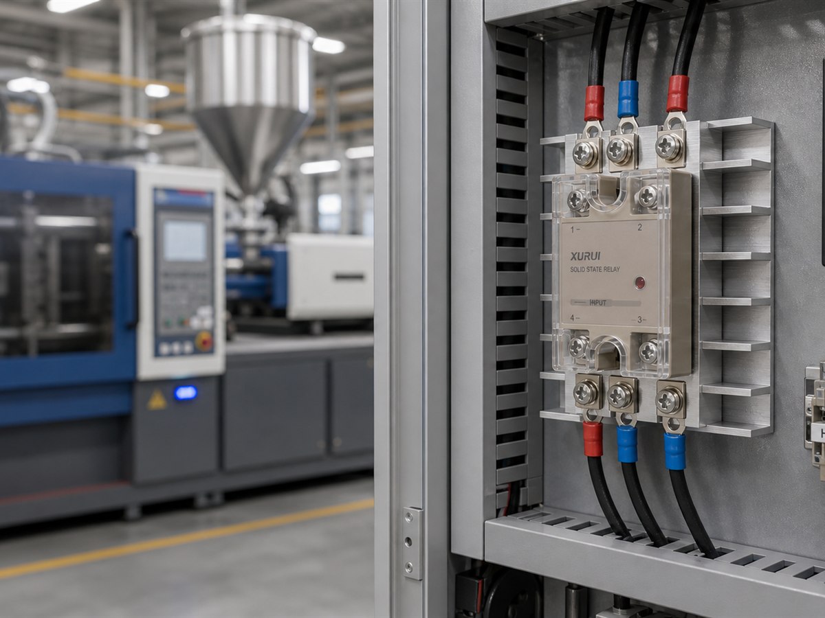
Injection molding OEMs should select a solid state relay as part of the complete heater circuit. The SSR must match the heater voltage, phase, cold current, controller output, switching method, heat sink, protection, and cabinet temperature.
This guide shows OEMs how to define those requirements for barrel, nozzle, mold, and hot runner zones. It then turns the requirements into an RFQ and production qualification plan.
Where Do Solid State Relays Fit in Injection Molding Machines?
Solid state relays fit electric heater circuits that cycle frequently under PLC or PID temperature control. The XURUI SSR-2025 catalog lists injection molding machinery among its application fields, but the machine design still determines the required SSR type and rating.
Barrel and Nozzle Heater Zones
Barrel heater bands warm the plasticizing cylinder, while the nozzle zone keeps the melt path near the required process temperature. OEMs usually assign each controlled zone its own temperature sensor and controller output, which allows them to tune heat delivery along the barrel.
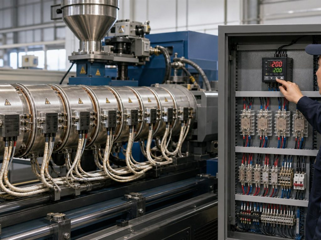
Frequent, time-proportional control makes an on-off AC SSR a common fit for conventional resistance heaters. Zero-cross switching usually suits this job because the output starts conducting near an AC voltage zero crossing. The OEM must still confirm heater construction. If the heater supplier specifies much lower resistance when cold, engineers must include the resulting startup current instead of sizing the SSR only from hot operating current.
Mold and Hot Runner Heater Zones
Hot runner manifolds and nozzles may contain multiple heater zones with separate thermocouples. The OEM electrical schematic should identify each heater’s wattage, resistance, current, control zone, and any heaters connected together.
Assign SSR channels from the machine’s control-zone map. Independently controlled zones need separate switching channels. Combining unrelated zones under one SSR removes independent control and makes an open heater, wiring fault, or temperature imbalance harder to locate.
Which Electrical Specifications Define the Right SSR?
Build a zone-level electrical schedule before choosing an SSR package or current class. Record the supply, heater, controller, switching, and fault requirements for each zone.
Heater Supply Voltage, Phase, and Load Type
Match the SSR output to the branch circuit. A single-phase AC heater needs an AC-output SSR whose load-voltage range covers the nominal supply and expected variation. A three-phase heater needs either a rated three-phase SSR or a documented arrangement of single-phase devices. Record the phase-to-phase voltage, switching topology, grounding method, and required response to an open phase.
Do not classify every heater as a simple steady resistance. Record the heater material, transformer use, rectification, and expected inrush. An AC SSR relies on the load current reaching zero to turn off, so it is not a substitute for a DC-output SSR. The differences between AC and DC SSR use explain why the output device must match the load current type.
Heater Current, Cold Resistance, and Derating Margin
Calculate nominal current for each zone, then verify it against measured or supplier-provided resistance. For a single-phase resistive heater, the starting estimate is I = P / V. For a balanced three-phase resistive load, the line-current estimate is I = P / (sqrt(3) x VLL). Use the actual circuit arrangement when heaters connect line to neutral or when phase loading is uneven.
Next, calculate cold current from the lowest expected heater resistance and highest expected supply voltage. Check that value against the SSR’s repetitive current, nonrepetitive surge curve, and permitted load type. Then apply the manufacturer’s ambient-temperature and mounting derating curve. Reserve margin for supply variation, restricted panel airflow, and nearby heat sources instead of treating the catalog rating as the available cabinet current.
PLC or PID Controller Output and SSR Input
The controller output must drive the SSR input fully on and release it fully off. Confirm the controller’s output type, voltage range, available current, off-state leakage, polarity, and number of SSR inputs driven by one channel. Then compare those values with the SSR’s pickup and release limits across the specified temperature range.
A voltage-pulse PID output usually drives an on-off SSR through time-proportional control. A 4 to 20 mA or 0 to 10 V analog output may instead command a power regulator. The XURUI catalog model key includes DC, AC, 4 to 20 mA, 0 to 10 V, and potentiometer control options, but the OEM must check the exact series before releasing the schematic.
On-Off SSR or Phase-Angle Voltage Regulator
Use an on-off SSR when the controller varies average heater power by changing the ratio of on time to off time over a control period. This method fits conventional barrel and nozzle heater zones and keeps the power circuit simple.
Use a phase-angle voltage regulator only when the thermal process needs power modulation within each AC cycle and the controller supports that method. A regulator changes the firing angle and produces a different current waveform, so the OEM must review harmonics, electromagnetic compatibility, RMS current, and heat dissipation. XURUI’s phase-angle AC solid state voltage regulator is a separate product type from an XSSR on-off relay and should appear as such on the bill of materials.
Zero-Cross or Random Turn-On Switching
Choose zero-cross turn-on for ordinary on-off or time-proportional control of compatible AC resistance heaters. Starting near the voltage zero crossing usually reduces conducted and radiated switching noise compared with random turn-on. Choose random turn-on when the control method requires firing at a selected point in the AC waveform. Phase-angle control needs this capability, but random turn-on can increase electrical noise without improving a slow thermal process.
How Should OEMs Size the Heat Sink and Protection Circuit?
Size the SSR, heat sink, airflow, fuse, surge protection, and shutdown device as one system. Oversizing the SSR current rating does not correct a poor thermal path or missing fault isolation.
Calculating SSR Power Dissipation
For an SCR or triac output, estimate conduction loss from the datasheet on-state voltage and RMS load current: P_loss ~ V_on x I_RMS. Use the manufacturer’s loss curve when available because on-state voltage changes with current and junction temperature. For a MOSFET output, the first estimate is P_loss ~ I_RMS^2 x R_on.
Use RMS current under the real switching waveform. A phase-angle regulator can produce a nonsinusoidal current, so a simple nominal-current estimate may understate device and conductor heating. Add the losses of all SSRs mounted in the same cabinet when calculating enclosure heat load.
Sizing the Heat Sink for Cabinet Conditions
Select the heat sink from the SSR supplier’s load-current and ambient-temperature curves. Check the maximum summer air temperature at the SSR inlet, nearby heat sources, altitude, mounting direction, spacing, airflow, interface material, flatness, and mounting torque. Do not use room temperature as the cabinet design temperature.
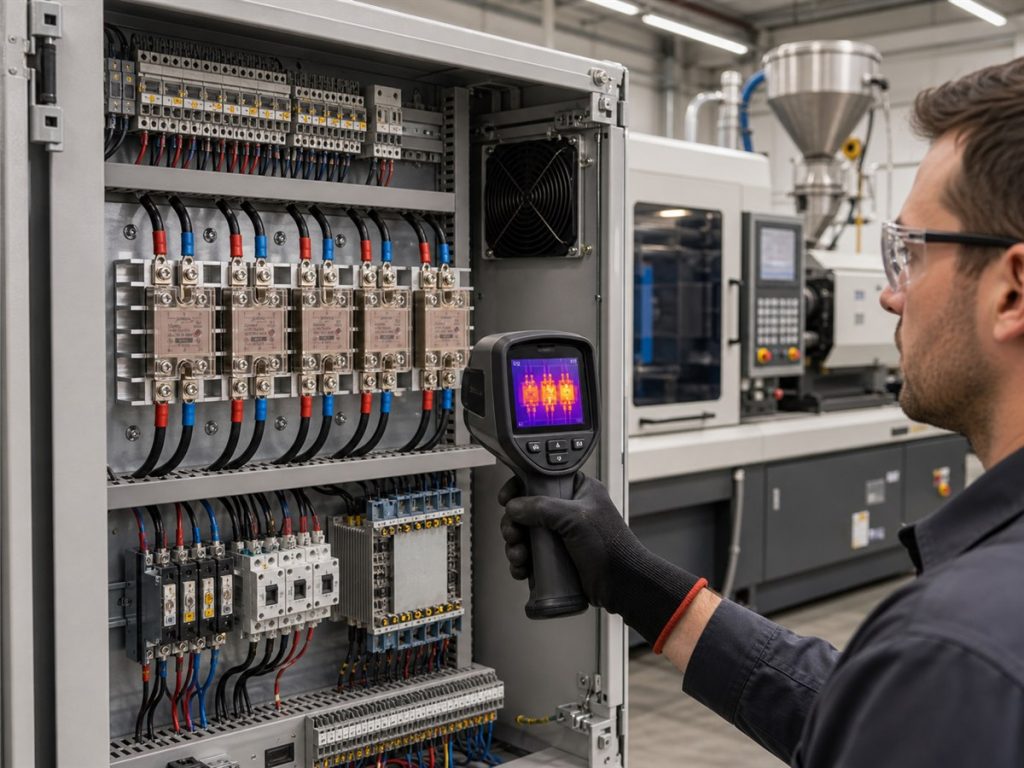
Thermal resistance, expressed in degrees Celsius per watt, shows how much temperature rises for each watt of loss. A lower value indicates a more effective thermal path. A first-pass calculation can compare the allowed base or junction temperature rise with total dissipation, but the final design should follow the exact SSR and heat sink curves. Dense mounting can also reduce the permitted load current because adjacent devices heat the same cabinet air.
The heat sink requirements for solid state relays depend on the actual load and mounting conditions. Run the completed panel until the SSR, heat sink, and cabinet temperatures stabilize before accepting the thermal design.
Selecting Overcurrent and Surge Protection
Use branch protection for conductors and fire risk, then add semiconductor protection where the SSR manufacturer requires it. A standard circuit breaker may not clear quickly enough to protect an SSR output die. Match a high-speed fuse by rated voltage, available fault current, interrupting rating, current, and total clearing I squared t against the SSR’s protection data.
Choose surge suppression from the supply and load behavior. A correctly rated metal oxide varistor, RC network, or other specified device may limit transient voltage, but the part value and placement must follow the SSR manufacturer and the machine’s electromagnetic compatibility design. A complete SSR protection circuit should coordinate the semiconductor fuse with the branch protective device and the separate device that removes heater power after an SSR fault.
Adding Independent Overtemperature Shutdown and Safe Isolation
Do not rely on the process PID, its thermocouple, and its SSR as the only overtemperature protection. SSRs can fail shorted, which may leave a heater on after the control signal turns off. Use an independent temperature limit device with its own sensor where the risk assessment requires one, and let that device remove heater power through a suitably rated contactor or disconnecting device.
Where overheating creates a hazard, the high-temperature limit and power-interrupting device should operate independently from the process controller and its SSR. Include the limit circuit in scheduled functional tests. Provide a lockable isolation point for service, and verify stored energy, backfeed, and all energized phases before work begins.
How Should OEMs Qualify an SSR for Production?
Production qualification must verify electrical fit, thermal margin, protection coordination, mounting, and supplier control. A catalog current rating does not prove that the SSR will operate within its limits inside the machine cabinet.
Defining RFQ Load and Control Requirements
Give suppliers a zone schedule instead of a general request for an injection molding SSR. Include:
- Nominal and maximum supply voltage, frequency, and phase.
- Heater type, wattage, hot current, minimum cold resistance, and measured startup current.
- Number of zones, switching channels, duty cycle, and expected control period.
- PLC or PID output type, voltage, current, leakage, and polarity.
- Zero-cross, random turn-on, on-off, or phase-angle control method.
- Maximum cabinet ambient temperature, mounting orientation, airflow, and spacing.
- Required heat sink, fuse, surge device, terminals, and touch protection.
- Required standards, market approvals, service life target, traceability, and change-notification terms.
Xurui Switch lists product families for single-phase, three-phase, DIN rail, monitoring, protection, and voltage-regulator applications.
When building the shortlist, use the solid state relay range to separate on-off XSSR families from XSSVR voltage regulators before requesting exact series data. Final approval still depends on a series datasheet, thermal data, samples, and the machine’s target market requirements.
Verifying Datasheets and Certification Scope
Confirm the exact order code instead of approving only the family name. Review input limits, load-voltage range, minimum load current, off-state leakage, on-state voltage, surge current, dv/dt, insulation, operating temperature, derating curves, terminal torque, and dimensional drawing. Ask for the matching heat sink data and protection recommendation.
Certification marks must cover the exact part number and intended rating. Check the certificate holder, standard, model list, voltage and current scope, conditions of acceptability, and revision status. Because certification scope can vary by series, confirm the exact model certificate before adding the mark to the OEM compliance file.
Confirming Mounting and Replacement Dimensions
Compare the base footprint, hole centers, terminal locations, required clearances, heat sink envelope, finger-safe cover, DIN rail position, and wire-bend space. Include the installed heat sink and connector arrangement in the CAD review. Two relays with the same current rating may require different panel space or mounting pressure.
Define whether a field replacement must match the original form, fit, and function or whether the service process permits an adapter and wiring change. Control the mounting compound, screw grade, torque, terminal hardware, and assembly instruction because a loose power terminal or poor thermal interface can create concentrated heat.
Testing Samples Under Worst-Case Operating Conditions
Test samples in a representative panel at the highest allowed supply voltage, maximum cabinet ambient, lowest expected heater resistance, densest mounting, and expected duty cycle. Include startup from cold, normal cycling, loss of airflow, sensor faults, open-heater faults, output-short detection, and shutdown response where the machine design supports those tests.
Record heater RMS current, SSR input voltage, output voltage drop, terminal temperature, SSR base or case temperature, heat sink temperature, cabinet air temperature, and stabilization time. Inspect the current waveform when the design uses phase-angle control. Repeat critical tests after thermal cycling and any connection-maintenance step specified by the terminal manufacturer.
Maintaining Batch Traceability and Change Control
Record the manufacturer, exact part number, date or lot code, approval documents, sample-test report, and approved substitute list in the product lifecycle system. Link each machine serial number or production batch to the installed SSR lot when field risk justifies that level of traceability.
Require advance notice for changes to the semiconductor die, optocoupler, molding compound, terminals, internal protection, factory, dimensions, labels, certification, or heat sink. Set the requalification depth from the change risk. A label revision does not require the same testing as a new output device or thermal construction.
Frequently Asked Questions
Can One SSR Control Multiple Heater Zones, or Does Each Zone Need Its Own SSR?
One SSR can control multiple heaters when they share one control command, sensor loop, and shutdown response. Add their current, verify the cold-start load, and protect the wiring as one zone. This arrangement makes individual heater faults harder to diagnose, so independently regulated zones need separate SSR channels.
Can OEMs Connect SSRs in Parallel to Increase Heater Current Capacity?
No. Do not parallel SSR outputs to increase current capacity unless the manufacturer provides a specific current-sharing design. Small differences in on-state voltage can produce uneven current sharing, so use one properly rated device or a manufacturer-approved arrangement.
Can a Higher-Current SSR Replace the Original Unit Without Changing the Heat Sink?
Not automatically. The replacement may have a different on-state voltage, baseplate, thermal resistance, mounting pressure, or derating curve. Recalculate loss, confirm mechanical contact with the heat sink, and test the assembly at the worst cabinet temperature before approval.
Does Frequent PID Switching Shorten a Solid State Relay’s Service Life?
Frequent time-proportional switching does not create mechanical contact wear because an SSR has no moving contacts. Service life still depends on junction temperature, surge current, overvoltage, mounting quality, and operation within the switching and thermal ratings. Use a controller cycle time supported by both the SSR and the heater process.
How Can Technicians Tell Whether Overheating Comes From the SSR, Thermocouple, or Zone Wiring?
Compare the controller command, measured heater current, zone temperature, SSR voltage drop, terminal temperature, and heat sink temperature at the same time. Current that continues when the output command is off points toward a shorted SSR or wiring bypass. A false temperature reading points toward the thermocouple or input circuit, while a hot terminal with normal current usually points toward a loose, damaged, or undersized connection.
XURUI Engineering Team






