
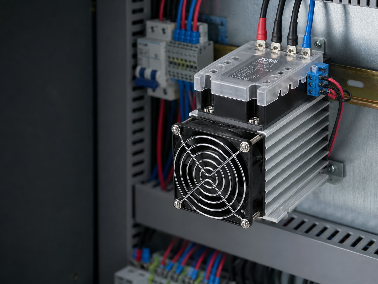
Choose a solid state contactor for frequent switching only when the system can manage semiconductor heat, off-state leakage current, and a possible shorted-output failure. Unlike a mechanical contactor, it controls load current without moving power contacts.
Selection depends on the load waveform, inrush current, duty cycle, control signal, cooling method, and fault response. This guide helps panel builders, OEM engineers, and industrial buyers decide whether a solid state contactor fits the application and what to verify before ordering one.
What Is a Solid State Contactor and How Does It Work?
A solid state contactor uses a low-power control input to switch one or more semiconductor output channels. It switches load power like a contactor, but it does not create the physical gap found between open mechanical contacts.
Control Signal and Switching Circuit
The control circuit converts a command from a PLC, temperature controller, sensor circuit, or relay output into gate drive for the power semiconductor. The same input and output sequence explains how a solid state relay works.
- The input receives a control voltage or current within its specified operating range.
- An internal drive circuit activates the output. Optical or transformer isolation may separate the input from the load circuit, depending on the design.
- When the command ends, an AC thyristor or triac stops conducting at a current zero. A transistor output for a DC load turns off through its drive circuit.
Check the exact input range, input current, isolation rating, response time, and off-state behavior in the product datasheet. These values vary by series.
Semiconductor Load Switching
The output device determines which load the contactor can switch. AC designs commonly use thyristors or triacs, while DC designs may use power transistors such as MOSFETs. The selected technology sets the voltage range, polarity, on-state voltage drop, leakage current, and turn-off behavior.
AC turn-on mode adds another selection condition:
- Zero-cross switching turns on near an AC voltage zero and often fits resistive heaters.
- Instantaneous or random turn-on switching responds without waiting for a voltage zero and fits applications that require immediate turn-on.
- Phase-angle control varies power within each AC cycle and requires a voltage regulator or power controller rather than a standard on-off contactor.
The switching mode does not establish load suitability by itself. Confirm the motor, transformer, lamp, heater, or capacitive-load rating stated by the manufacturer.
How Does a Solid State Contactor Compare with Other Switching Devices?
A solid state contactor shares its switching principle with a solid state relay, while its circuit role resembles an electromechanical contactor. Compare the full assembly and its approved load duty because product names do not define a consistent package across manufacturers.
Solid State Contactor vs Solid State Relay
The two terms overlap. A solid state contactor often packages one or more solid state relay channels with contactor-style terminals and a specified thermal arrangement. A standalone solid state relay may require a separately selected heat sink, fan, or multi-phase wiring scheme.
| Selection point | Solid state contactor | Solid state relay |
|---|---|---|
| Switching element | Semiconductor | Semiconductor |
| Typical scope | Matched load-switching assembly | Component, module, or integrated unit |
| Phase arrangement | Often supplied for single-phase or three-phase circuits | Available as single-channel or multi-phase devices |
| Thermal design | Often defined as part of the assembly | Integrated on some models; selected separately on others |
| Main buyer check | Verify the assembly rating | Verify the relay and cooling system together |
Some integrated solid state relays already include thermal hardware. The product label alone does not tell a buyer what the package includes, so check the datasheet.
Solid State Contactor vs Electromechanical Contactor
The main difference is how each device carries and interrupts current. The resulting tradeoffs also apply when comparing a solid state relay with a mechanical relay.
| Decision factor | Solid state contactor | Electromechanical contactor |
|---|---|---|
| Moving power contacts | None | Yes |
| Repetitive switching | Supports fast, frequent switching when thermally sized | Limited by contact wear and mechanical life |
| Operating noise | No contact click | Audible coil and contact action may occur |
| Conduction loss | Produces semiconductor heat while on | Usually lower across closed main contacts |
| Off state | Passes a small leakage current | Open contacts provide physical separation |
| Common fault concern | Output may fail shorted | Contacts may weld or fail to close; coils and mechanisms may also fail |
| Status feedback | Requires a documented monitor or separate sensing | Mechanically linked auxiliary contacts may be available |
An off control signal does not make a solid state contactor safe for service work. Use a disconnecting device that has an approved isolating function before maintenance.
When Should You Use a Solid State Contactor?
Use a solid state contactor when the switching rate would shorten mechanical contact life or when contact noise disrupts the application. The exact device must still carry a rating for the load category and operating cycle.
Frequently Switched Motor Loads
A motor-rated solid state contactor may fit repetitive direct-on-line starts when its surge and thermal curves cover the complete start cycle. Reversing duty requires a purpose-built reversing unit or an approved circuit with electrical interlocking and the specified transfer delay.
Do not size the device from motor running current alone. Verify:
- line voltage and frequency
- motor full-load current
- starting-current factor and starting time
- starts per hour and the complete load cycle
- cabinet temperature and cooling conditions
- separate overload and short-circuit protection
Resistive Heating Loads
Resistive heaters are a common application because temperature controllers may cycle them repeatedly. Zero-cross switching often suits this duty, but long on periods can produce sustained heat in the semiconductor. Calculate power loss from the manufacturer’s on-state data, then apply the specified heat sink, airflow, mounting orientation, and ambient-temperature derating.
Lighting and Other Repetitive Loads
Lighting, solenoids, valves, and transformers may suit solid state switching, but their inrush and transient behavior differs from resistive heating loads.
| Load type | Main electrical stress | Selection check |
|---|---|---|
| Incandescent lamp | High cold-filament inrush | Compare peak current and duration with the surge curve |
| LED driver or electronic power supply | Capacitive input-current surge | Confirm the approved capacitive or lamp-load rating |
| Solenoid or valve coil | Inductive turn-off and commutation stress | Check the inductive-load rating and suppression method |
| Transformer | Magnetizing inrush | Check peak current, energization conditions, and switching mode |
A zero-cross output may reduce turn-on disturbance for some AC loads. It does not remove inrush or extend a resistive-load rating to other load categories.
How Should Buyers Select a Solid State Contactor?
Select a solid state contactor from the actual electrical and thermal duty, then verify protection, installation space, and documentation. Give suppliers the load data, control signal, switching cycle, ambient conditions, and required approvals with the request for quotation.
Matching Load Voltage, Current, Phase, and Poles
Match the power circuit before comparing current ratings:
- Confirm whether the load uses AC or DC power.
- Keep the operating voltage within the rated load-voltage range and below the specified blocking limit.
- Identify single-phase or three-phase service and the load connection.
- Confirm how many circuit legs the approved design switches. Some three-phase arrangements switch two legs, while others switch all three.
- Apply the current rating for the stated load category, ambient temperature, heat sink, and mounting conditions.
Checking Inrush Current, Duty Cycle, and Switching Frequency
Use the complete current profile because nameplate current does not show starting stress or accumulated heat.
- Record the normal current, peak inrush, inrush duration, on time, off time, starts per hour, and highest expected cabinet temperature.
- Compare each event with the nonrepetitive surge curve and any repetitive switching graph in the datasheet.
- Apply the manufacturer’s thermal derating and confirm that the assembly can remove heat over the full cycle.
Motor, transformer, lamp, and capacitive loads may require a higher nominal current than the steady load current suggests.
Matching the Control Input and Switching Mode
Match the control source to the input circuit, then select the turn-on mode for the load.
| Control or load condition | Required check |
|---|---|
| PLC transistor output | Input voltage, polarity, required input current, and PLC off-state leakage |
| Relay or AC controller output | Supported input type, voltage range, and minimum operating current |
| Resistive AC heater | Zero-cross mode when the device and control method permit it |
| Immediate AC turn-on requirement | Instantaneous or random mode with an approved load rating |
| Proportional AC power control | Phase-angle regulator or power controller, not a standard on-off contactor |
Planning Heat Dissipation and Short-Circuit Protection
Plan cooling and fault protection as parts of the contactor assembly. The same coordination principles used to protect a solid state relay apply to the semiconductor channels inside the contactor. Semiconductor junctions can overheat before the enclosure or panel surface appears unusually hot.
- Calculate dissipation from the manufacturer’s on-state voltage or power-loss data.
- Select the specified heat sink, thermal interface, mounting orientation, spacing, and airflow.
- Account for blocked airflow or fan failure when the design uses forced cooling.
- Coordinate the branch protection with the semiconductor’s short-circuit limits and the manufacturer’s fuse data.
XURUI lists XSSC single-phase and three-phase contactors within its solid state relay range. Each XSSC configuration pairs specified XSSR devices with matched heat sinks. The catalog shows fans on the three-phase configurations and on one high-current single-phase configuration. Treat each listed combination as a complete thermal assembly.
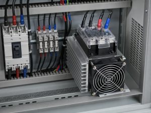
A standard circuit breaker may protect the conductors without clearing quickly enough to protect the semiconductor. Use the specified fuse type and surge suppression. If a shorted output could leave a hazardous load energized, add fault monitoring and an independent device that can disconnect power.
Confirming Panel Fit and Certification Scope
Approve the panel layout and compliance documents for the complete installed assembly, not just the switching module.
| Review area | Items to confirm |
|---|---|
| Installed envelope | Heat sink, fan, terminal covers, wire bend radius, and service clearance |
| Thermal layout | Mounting orientation, airflow path, spacing, and nearby heat sources |
| Wiring | Conductor size, terminal torque, grounding, and protective-device location |
| Product documentation | Current datasheet, wiring diagram, derating curves, and installation instructions |
| Approval scope | Exact series, voltage, load category, certification mark, and target region |
IEC 60947-4-2 covers AC semiconductor motor controllers, starters, and soft starters. If the application involves motor switching, confirm that a current certificate or test report covers the exact selected series, required edition, and load category. A standard named in a catalog does not prove that every model holds every certification.
Before approving a production order, request the current series datasheet, certificate, and bill of materials for the contactor, heat sink, and fan combination from XURUI Switch.
FAQs
Does a Solid State Contactor Replace a Motor Overload Relay?
No. A solid state contactor switches motor current but does not provide overload protection unless the exact product includes a documented and certified overload function. Most motor circuits still need a coordinated overload relay or motor protection device, plus short-circuit protection selected for the motor, starter arrangement, and applicable electrical rules.
Can a Solid State Contactor Be Used with a VFD or Soft Starter?
Yes, but only when the contactor and drive manufacturers approve the circuit position and switching sequence. Do not assume the contactor can switch a variable frequency drive or soft starter output. Install and operate the device only where both manuals permit the waveform, timing, and fault response.
Does a Solid State Contactor Have Auxiliary Contacts for Status Feedback?
Not necessarily. A solid state contactor may lack mechanically linked auxiliary contacts, and an input indicator confirms only the command state. Check for a documented monitoring output. If the controller must verify load operation, use that output, a current sensor, or another circuit that measures the actual load state.
Can a Solid State Contactor Fail in the On State?
Yes. A damaged thyristor, triac, or transistor can fail shorted, which may keep the load energized after the control signal turns off. If that condition could damage equipment or create a hazard, monitor the load state and use an independent contactor, breaker, or disconnecting device to remove power.
Why Is Voltage Still Present When a Solid State Contactor Is Off?
Off-state leakage current and internal snubber components can leave measurable voltage across the load. A high-impedance meter may display this voltage even when the available current cannot operate the load. Isolate power before service, then compare the reading with the datasheet’s leakage-current value and prescribed test method.
XURUI Engineering Team






