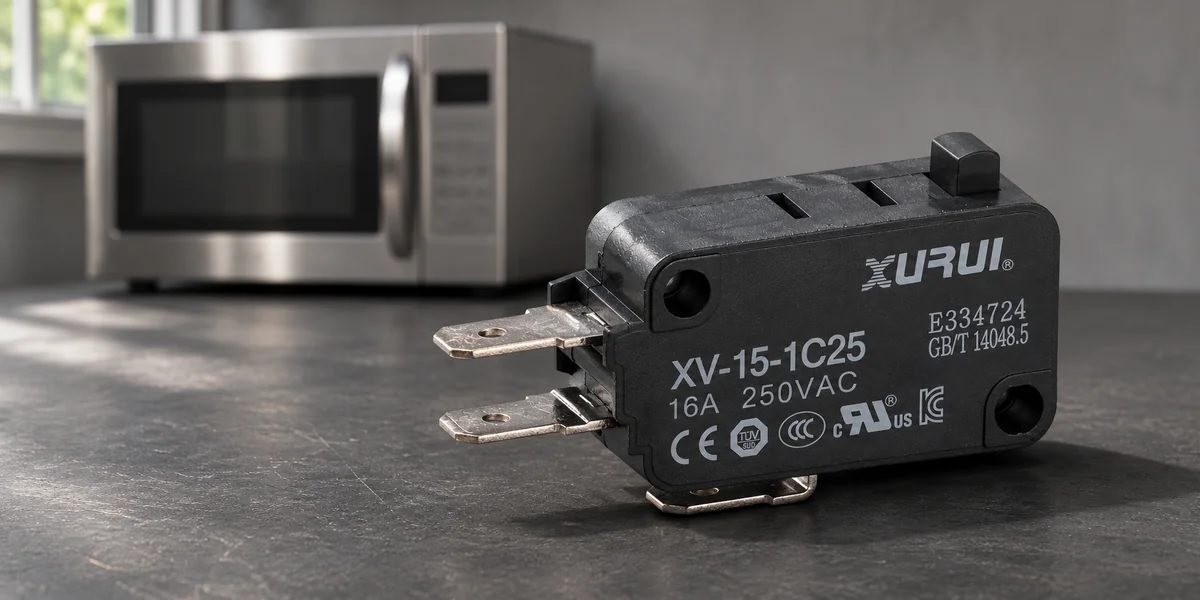
A microwave door switch changes electrical contact states as the door latch moves. For reliable door detection, the switches must change state in the correct order, with enough actuator travel to operate and release consistently.
This guide focuses on common mechanical microwave interlocks. It explains how contact timing and assembly variation affect door signals and what to check when replacing a switch before returning the oven to service.
How Microwave Door Switches Detect a Closed Door
The door latch moves the switch actuators, opening or closing their internal contacts. A common arrangement includes:
- A primary interlock that interrupts the microwave power circuit.
- A secondary interlock that provides another way to interrupt that circuit.
- A monitor switch that triggers a protective response when an interlock failure creates the fault conditions it is designed to detect.
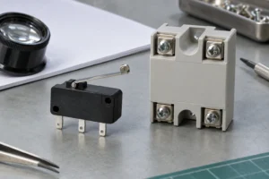
The control board may not receive a separate signal from each interlock. Some ovens have an additional switch specifically for sensing door position. Many designs use snap-action micro switches. Their spring mechanism transfers the contacts quickly once the actuator reaches its switching position. Normally open (NO) and normally closed (NC) describe the contacts when the actuator is unoperated. These labels do not automatically correspond to an open or closed oven door.
Why Door Switch Contact Sequence Matters
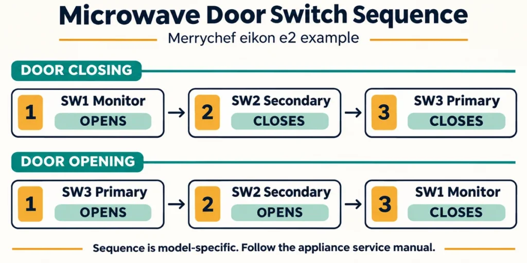
Contact sequence determines which electrical path changes first as the door moves. The example below follows the Merrychef eikon e2 arrangement. Other models may use different circuits, switch labels, or switching relationships.
Door Closing Sequence
The monitor contact opens before the secondary and primary interlocks close:
- The monitor switch, SW1, opens.
- The secondary interlock, SW2, closes.
- The primary interlock, SW3, closes.
This sequence opens the monitor’s short-circuit path before completing the microwave supply path. The manual specifies that the primary switch must switch the load current.
Door Opening Sequence
When the door opens, the supply interlocks open before the monitor contact closes:
- The primary interlock, SW3, opens.
- The secondary interlock, SW2, opens.
- The monitor switch, SW1, closes.
The supply path should be interrupted before the monitor contact closes. If the required interlocks remain closed, the monitor circuit can cause the protective fuse to open. This protective response indicates a fault that needs investigation and should not be dismissed as a false display message.
How Actuation Tolerance Affects Door Signals
Actuation tolerance is the allowed variation in switching position or movement. The door assembly must accommodate that variation while keeping each switch within its permitted travel.
Operating and Release Positions
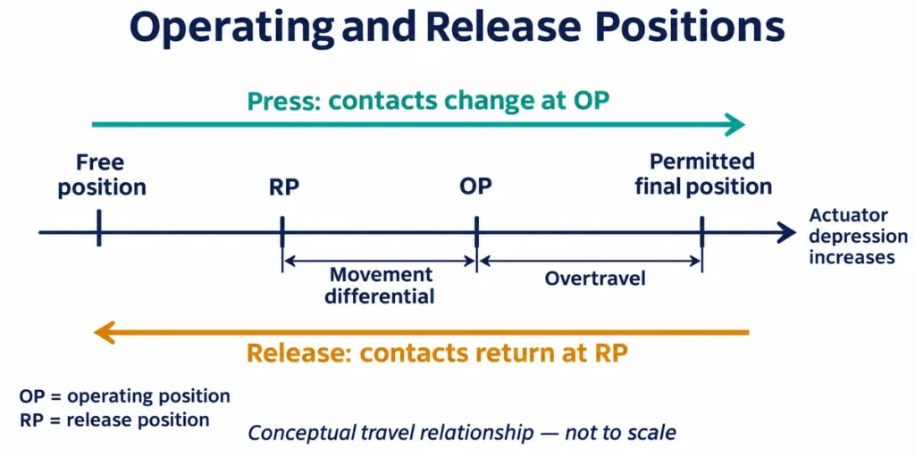
The operating position (OP) is the point where the contacts change state as the actuator is pressed. At the release position (RP), they return to their original state as pressure is removed.
The travel between these positions is movement differential, often called micro switch hysteresis. Movement differential separates the operating and release events. Manufacturing tolerance describes how far a specified value is allowed to vary. Closing the door must push the actuator far enough beyond its operating point to leave adequate margin. Opening the door must allow it to return past its release point.
Tolerance Stack-Up
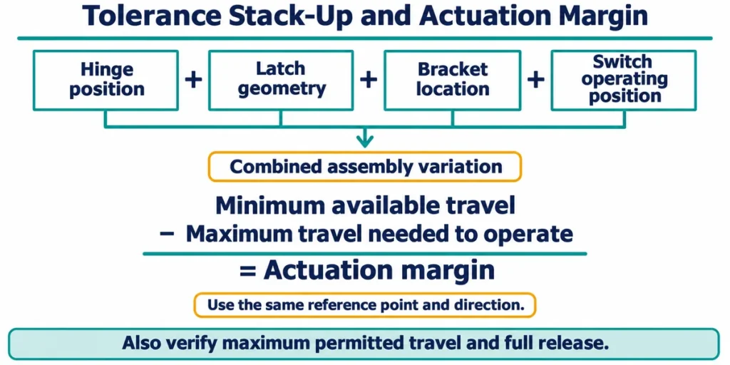
Tolerance stack-up is the combined effect of variation in hinge position, latch shape, bracket location, and switch operating position. Parts can each meet their specifications yet leave too little actuator travel once assembled. Using the same reference point and direction, compare the minimum available travel with the maximum needed to operate the switch. A zero or negative difference leaves no actuation margin.
Also confirm that maximum travel stays within the permitted final position and that opening the door allows full release. Overtravel, the movement beyond the operating point, must remain within the specified stroke limits.
Wear and Temperature Effects
Wear and temperature can change the movement available after assembly. Worn latch surfaces, loose holders, or hinge movement can reduce the travel transferred to the actuator. Thermal expansion can also change door fit. Merrychef’s eikon e2 adjustment procedure specifically accounts for door-seal expansion.
For a fault that changes with temperature, check door fit and switch operation under the conditions specified in the service procedure. Adjusting a bracket to address one symptom can change another switch’s timing.
Common Causes of False Door Signals
Symptoms can help narrow the investigation, though none identifies a failed component on its own. First establish whether the oven is displaying a normal control message or reporting a door-detection fault.
| Observed Symptom | Possible Cause | Verification Focus |
| Door appears closed, but the oven reports it open | Insufficient latch movement or excessive door gap | Compare door fit and installed switching position with the model’s requirements |
| Door position changes the reported state | Hinge wear, loose holder, or marginal actuator travel | Inspect alignment and mounting stability |
| Switch passes an isolated test but fails when installed | Assembly prevents reliable operation or release | Check installed actuator movement through the complete door cycle |
| Replacement switch does not clear the fault | Incorrect part, terminal mapping, or unresolved assembly problem | Verify the specified replacement and trace the original fault |
| Fault began after latch or bracket work | Altered switch position or sequence | Compare mounting and switching order with the service documentation |
A continuity test shows whether a contact opens or closes under the test conditions. Separate checks are needed to establish correct installed travel, switching order, and control-board interpretation.
What to Check When Replacing a Microwave Door Switch
Start with the appliance manufacturer’s specified part or approved replacement. Qualified microwave service personnel must carry out internal inspections and adjustments using procedures that address stored high voltage and microwave exposure.
Electrical Compatibility
Match the contact arrangement, voltage, current, load type, and any specified inrush-current requirement. A rating for a resistive load does not establish suitability for a different load. For switches with a common (COM) terminal, check the COM, NO, and NC contact paths against the appliance wiring diagram. Similar terminal positions do not guarantee the same connections. A switch used in a low-current sensing circuit needs contacts suited to that load. A higher current rating alone does not guarantee reliable low-current switching.
Mechanical Compatibility
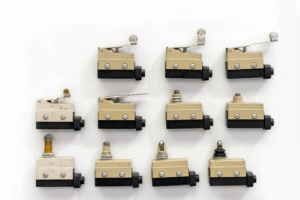
Compare mounting-hole spacing, actuator shape, terminal orientation, operating force, and travel characteristics. A switch can fit the holder yet change state at the wrong latch position.
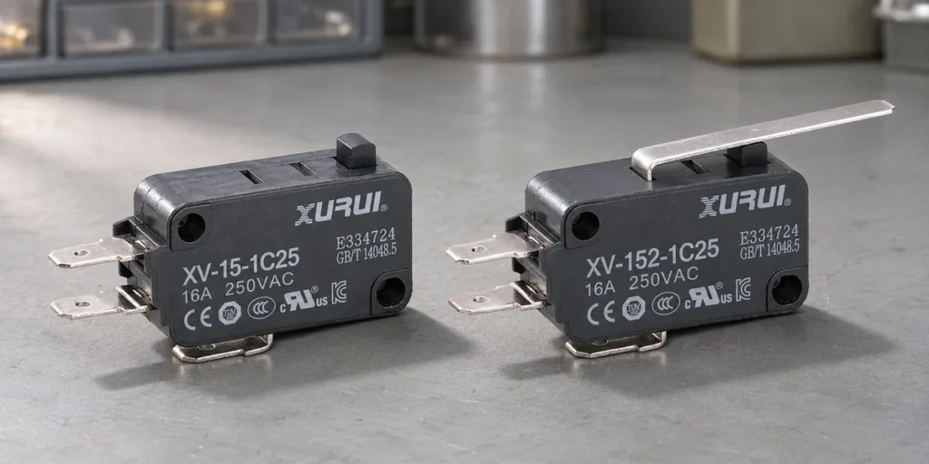
The XV-15 series actuator drawings show why variants within one switch family need separate dimensional checks. Use the drawings to compare geometry; an oven replacement still requires appliance-specific approval. Inspect the holder and latch as well. A new switch cannot restore movement lost through a damaged mounting feature.
Post-Replacement Validation
With the power safely isolated, a technician should first check the wiring, mounting, and contact states. The installed assembly then needs the model’s prescribed sequence and functional checks as the door is opened and closed repeatedly.
A click confirms mechanical action but does not establish electrical integrity. Continuity testing also cannot establish microwave containment. Complete the manufacturer’s required leakage and other service checks before returning the oven to use.
For component selection, discuss your switch requirements with XURUI. Include the original part number, latch drawing, and electrical load so the electrical and mechanical requirements can be reviewed.
Frequently Asked Questions
Can Software Debouncing Prevent False Door Signals?
Software debouncing can filter brief contact bounce at a controller input, but it cannot correct mechanical misalignment or an interlock fault. Bounce occurs when contacts briefly separate and reconnect during switching. Any filtering must preserve the required door-open response and cannot replace the specified interlock protection.
Why Do Some Microwaves Require the Door to Be Reopened Before Starting?
Some microwaves require the door to be opened and closed again as a safeguard against unintended starting. Whirlpool documents this behavior on certain models when the door has remained closed for about five minutes without cooking starting. Opening and closing the door resets that condition. The message alone does not establish a switch fault.
Can a Door Switch’s Cycle Rating Predict Its Service Life?
A cycle rating describes durability under specified conditions and does not guarantee a service life in years. Mechanical durability is tested with the contacts unenergized; electrical durability is tested under a specified load. Actual load, operating frequency, stroke, and environment affect service life. Dividing a catalog cycle count by daily door openings therefore gives only a rough usage projection.
External Sources
- Merrychef eikon e2 Service Manual — Door Interlock Adjustment
- OMRON Basic Switches — Explanation of Terms
- OMRON Basic Switches — Safety Precautions
- Whirlpool Technical Service Pointer W11493384 Rev. B — Microwave Door Is Not Closing
- Whirlpool — “Door” or “Open/Close” Display Message
- Texas Instruments — Common Logic Use Cases, Switch Debounce Section