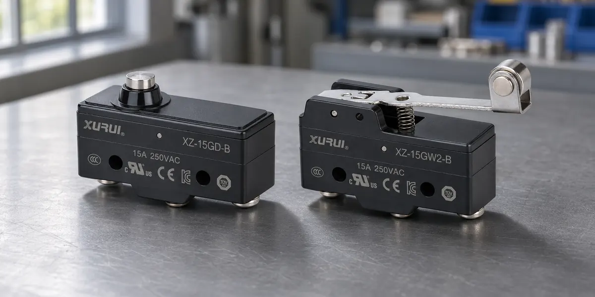
A 15A 250VAC micro switch can share its printed rating with another model yet fail as a replacement. The difference may lie in the load it switches, the motion that operates it, or the conditions around it.
Compatibility means preserving the equipment’s intended operation. Electrical ratings establish part of that case. The remaining evidence comes from the circuit, dimensional drawings, operating characteristics, and tests in the actual assembly.
What Does the 15A 250VAC Rating Actually Tell You?
The marking identifies an electrical rating of 15 amperes at 250 volts alternating current under the conditions specified for that model. It does not describe every load the switch can interrupt or establish a corresponding direct-current rating.
A complete micro switch selection considers the load category alongside voltage and current. A rating for a resistive load cannot automatically be applied to a motor with the same running current.
The marking also leaves mechanical details unstated. Two switches can carry identical electrical ratings while requiring different operating forces or reaching their switching points at different positions.
Check Electrical Compatibility Beyond the Printed Rating
Electrical compatibility depends on what happens when the contacts close and open, as well as the current flowing between those events.
Match the Rating to the Actual Load
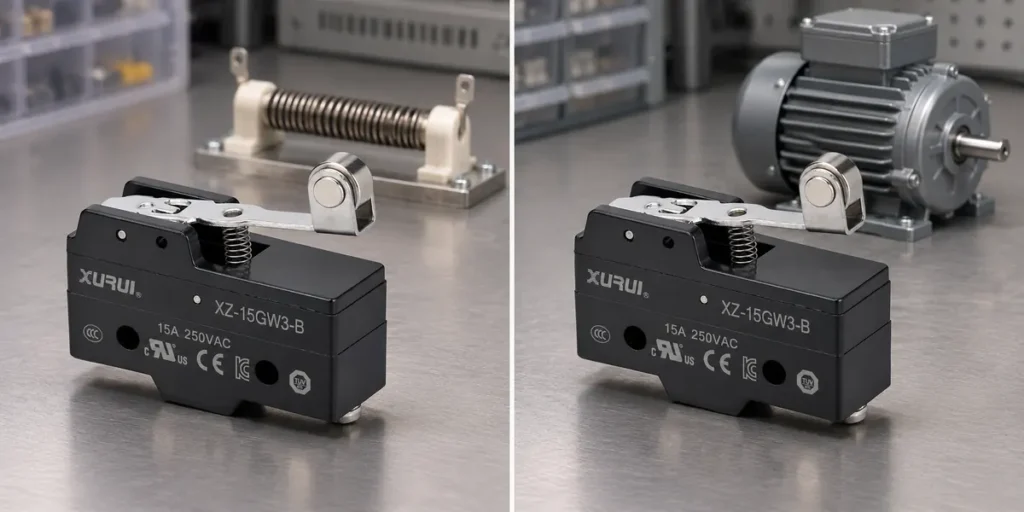
Start with the supply type, operating voltage, and load. A motor can draw substantially more current during startup than during normal running. An inductive load, such as a solenoid, produces a voltage transient when interrupted. These conditions increase contact stress and can promote welding or wear.
Compare the candidate’s documented rating for that load with the actual duty. A higher general current rating alone does not settle the question. OMRON’s basic-switch safety guidance specifically distinguishes steady-state current from inrush current when selecting contacts.
For DC applications, use the stated DC switching rating. AC current passes through zero each cycle, helping extinguish an arc; DC lacks that regular interruption.
Verify the Contact Function and Terminal Arrangement
The replacement must reproduce the circuit’s intended contact states. A single-pole, double-throw (SPDT) switch transfers a common connection between normally closed and normally open contacts. Two-terminal versions may provide only one of those functions.
In micro switch wiring, “normal” refers to the unactuated state. A switch held down by the installed mechanism may therefore behave differently from what a technician expects from the label alone.
Check the terminal diagram against both operating states. Similar terminal positions do not establish identical functions, and a matching connector does not prove correct wiring.
Confirm Suitability for Low-Level Signals
A switch capable of handling substantial current may perform poorly on a small control signal. Surface films on the contacts can obstruct conduction when the signal lacks sufficient energy to overcome them.
This makes contact material relevant to signal reliability. Gold-contact designs are commonly used for low-energy switching, while power-switching contacts serve different operating conditions.
Select a candidate whose documented low-load range covers the circuit. A minimum applicable load is a condition-dependent reliability reference, not a universal threshold shared by every micro switch.
Check Whether the Replacement Fits and Operates Correctly
Electrical suitability cannot compensate for a switch that the mechanism presses incorrectly. The installed movement must remain within the candidate’s permitted operating range.
Mounting Geometry
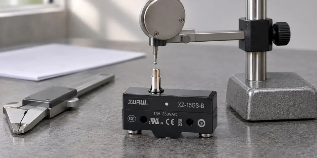
Compare body dimensions, mounting-hole locations, fastener requirements, and surrounding clearance. Use dimensioned drawings with tolerances; a product photograph cannot establish fit.
Terminal width, thickness, and orientation also affect the installation. A switch may fit its bracket while forcing the connector against a metal surface or putting tension on the wire.
The candidate need not duplicate every dimension. It must fit the available space, preserve required insulation clearance, and remain securely mounted without modifying the housing or mounting holes.
Actuator Characteristics
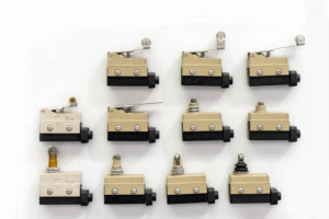
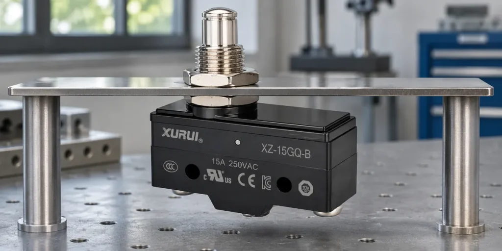
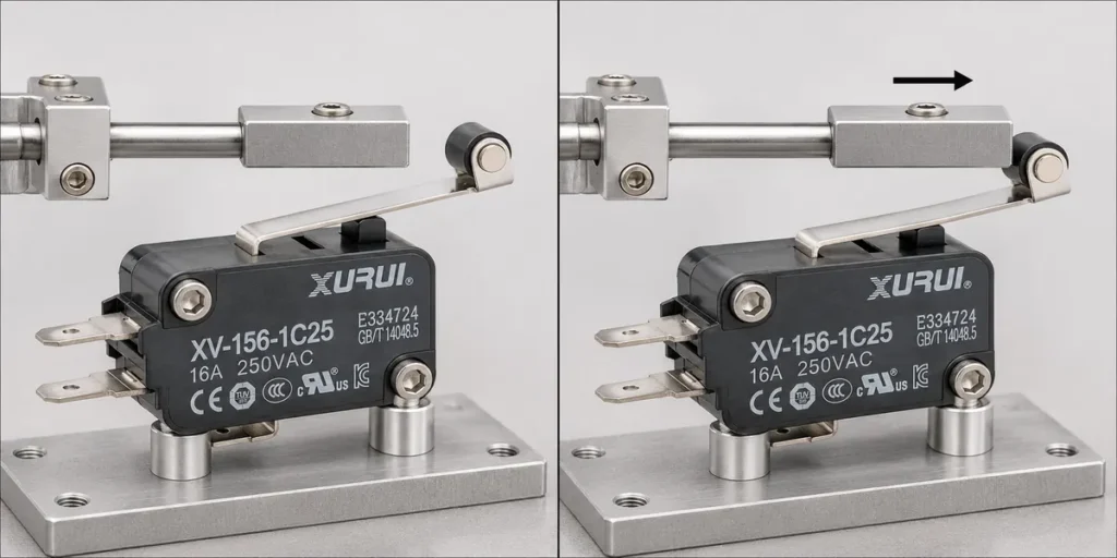
Different actuator types change how movement reaches the internal mechanism. A longer lever changes leverage and the contact path, so matching the body alone can shift the switching point.
Compare operating force, release force, and travel limits. Pretravel is movement before switching; overtravel is the permitted movement beyond the operating point. Movement differential is the distance between switching and release positions.
The mechanism must reliably cross both positions across the assembly’s tolerances. Too little movement can leave the contact state unstable. Excess movement can damage the switch. Available force and approach direction must also suit the selected actuator.
Confirm the Operating Environment
The same component can behave differently inside a dry control enclosure and beside a vibrating, contaminated machine.
Temperature Range
Use the temperature at the switch’s installed location, including nearby heat sources. Room temperature may say little about conditions beside a motor or heater.
Compare that exposure with the exact model’s operating range and any stated load restrictions. Storage-temperature limits do not establish operating capability.
Contaminant Exposure
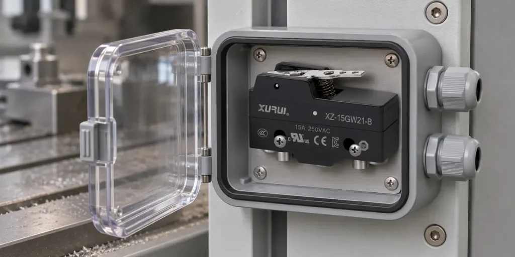
Dust can obstruct movement, while liquids and corrosive gases can affect contacts or internal parts. Protection therefore depends on the complete installed arrangement.
A waterproof micro switch still needs exposure-specific review. An ingress-protection rating describes specified particle and water tests; it does not automatically establish resistance to cleaning chemicals or oils. Housing, actuator seals, and terminal protection must suit the actual exposure.
Vibration and Shock
Check resistance to malfunction as well as resistance to damage. A switch can remain physically intact while its contacts open briefly during vibration, producing an unwanted control signal.
OMRON’s switch terminology distinguishes these performance categories. Compare their test conditions with the installation rather than treating a shock rating as proof of stable switching.
Verify Compatibility Before Approving a Replacement
Approval requires both a documented comparison and evidence that the installed replacement performs its intended function.
Specification Review
Establish the application requirement first. Copying the original component’s specifications can preserve an earlier selection error.
Use this recording template with actual documents and measurements. Mark missing information as unresolved.
| Compatibility Check | Application Requirement | Original Switch | Candidate Replacement | Evidence Required |
| Identification | Traceable configuration | Full model and suffix | Full model and suffix | Datasheets and drawing revisions |
| Electrical duty | Supply, load, and switching duty | Documented load rating | Documented load rating | Rating tables and load data |
| Circuit function | Required contact states | Terminal diagram | Terminal diagram | Circuit schematic |
| Installation | Space and connection limits | Dimensions and mounting | Dimensions and mounting | Toleranced drawings |
| Actuation | Available motion and force | Operating characteristics | Operating characteristics | Mechanism measurements |
| Environment | Actual operating exposure | Specified limits | Specified limits | Environmental specifications |
| Service life | Required operating duty | Relevant durability data | Relevant durability data | Test conditions and records |
Mechanical durability describes operation without an energized contact load. Electrical durability includes a specified load, so the two figures cannot substitute for one another.
Where equipment approval depends on the component, obtain evidence covering the candidate’s exact configuration and intended use. A logo alone does not establish that scope.
Application Testing
Disconnect power before installation, wiring, or continuity checks. Move the real mechanism through its full travel and verify the required contact states during actuation and release.
Then have qualified personnel perform controlled tests under representative electrical and environmental conditions. Check repeatable switching, reliable return, and the control system’s response. Include operating speed and frequency in the test plan.
A short functional test establishes immediate operation; it does not establish service life. Define acceptance criteria and any endurance testing from the required duty. Retain the tested model, drawing revision, installation details, and results.
For help reviewing a candidate, submit your replacement requirements to XURUI with the original model, load details, and installation drawing or photos.
Frequently Asked Questions
Can I Reuse the Existing Quick-Connect Connectors?
Potentially, if their specifications, condition, and equipment service instructions permit reuse. Match the receptacle to the blade’s width and thickness, wire size, and operating conditions.
TE Connectivity’s terminal guidance treats mating and retention characteristics as defined properties. Replace damaged, loose, or overheated receptacles rather than assuming that a connector which slides onto the blade remains serviceable.
Can a Long-Stored Spare Micro Switch Still Be Used?
Storage age alone does not answer the question. Packaging and exposure can affect terminals and contacts even when the switch has never operated.
Follow the model’s storage guidance and inspect the spare before installation. OMRON’s storage precautions address terminal discoloration and inspection after extended storage. Avoid applying one manufacturer’s inspection interval as a universal shelf life.
Why Does a Replacement Click but Fail to Work Correctly?
The click indicates mechanical movement, but it does not confirm a usable electrical path. Contaminated or damaged contacts can fail to conduct, and incorrect wiring can route the signal through the wrong contact.
OMRON’s troubleshooting guidance identifies several possible causes of a load failing to turn on. With power isolated, check continuity at the intended terminals through both operating states before investigating the external circuit.
XURUI Engineering Team