

Wiring a toggle switch is a classic DIY milestone, but unlabeled prongs and complex jargon can lead to blown fuses. Whether you’re upgrading a truck’s lighting with an LED toggle switch or restoring a vintage appliance, you need a clean, professional connection that works every time you flip the lever.
This guide provides a safety-first roadmap to take the guesswork out of your toggle switch wiring project. We’ll decode the anatomy of SPST and SPDT switches and master secure crimp connections so you get that satisfying click on your first try. Let’s dive into the basics of toggle switch anatomy.
Understanding Your Toggle Switch: What Do Those Pins Actually Mean?
Before you reach for your wire strippers, you need to know what kind of “gatekeeper” you’re holding. Not all toggle switches are created equal, and using the wrong one for your circuit logic is a recipe for a headache.
Decoding the Alphabet Soup: SPST, SPDT, and DPDT
You’ll see these acronyms on the packaging of almost every toggle switch, and they basically tell you how many “doors” the switch can open:
- SPST (Single Pole, Single Throw): This is your most basic on-off toggle switch. It has two pins. It either completes the circuit or breaks it. Think of it like a drawbridge; it’s either up or down.
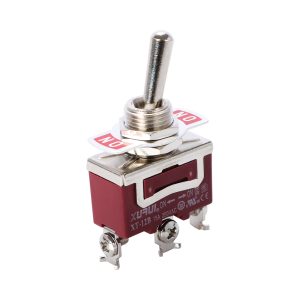
- SPDT (Single Pole, Double Throw): This 3-pin toggle switch is like a fork in the road—it toggles power between two different devices. For example, flip it up for Light A; flip it down for Light B.
- DPDT (Double Pole, Double Throw): Imagine two separate switches controlled by one single lever. This 6-pin toggle switch is often used for complex electronics or reversing the direction of a DC motor.
The “Third Pin” Mystery: Why Your Toggle Switch Has Three Prongs
If you bought an illuminated toggle switch that glows when turned on, you’ll notice an extra pin. This is essential for the internal light to function:
- Supply Pin: Takes the power in from the source.
- Load Pin: Sends the power out to your device.
- Ground Pin: This is the “odd man out.” It doesn’t power your device; it only exists to give the tiny LED inside the lighted toggle switch a path to ground so it can shine.
The Essential DIY Toolkit for Toggle Switch Installation
Trying to wire a toggle switch with just a kitchen knife and some tape is how electrical fires start. To do a “pro-level” job, gather these essentials:
- Professional Wire Strippers: The goal is to peel back exactly 1/2 inch of insulation without nicking the copper strands.
- Crimp Connectors (Spade Terminals): These are the gold standard for automotive toggle switch projects. They slide right onto the toggle switch terminals and provide a vibration-proof connection.
- Heat Shrink Tubing: Seals the toggle switch connection from moisture and prevents accidental “shorts.”
- A Digital Multimeter: This is your “truth detector.” It helps you test which toggle switch pins are connected before you ever hook up a live battery.
Related Reading: Differences Between a Rocker Switch and a Toggle Switch
Step-by-Step: Wiring a Standard 12V Toggle Switch
Let’s walk through the most common DIY scenario: adding a 12V toggle switch for a fog light or a cooling fan to a vehicle.
Step 1: Map Out Your Toggle Switch Terminals
Look closely at the casing of your toggle switch. Most manufacturers use a color code or small stamped letters.
- Pin 1 (Supply/Line): Connects to your battery (via a fuse!).
- Pin 2 (Load/ACC): This wire runs straight to your light or fan.
- Pin 3 (Ground/Earth): Connects to the metal chassis of your car (only required for illuminated toggle switches).
Step 2: Prepare the Wires and Fuse
Safety first! Always place an In-line Fuse on the wire coming from the battery. If a wire ever rubs against a metal edge and shorts out, the fuse will pop, saving your toggle switch and your vehicle from a fire.
Step 3: Make the Physical Connections
Slide your Power wire onto the toggle switch Supply pin, your device wire onto the Load pin, and your Ground wire to a clean, unpainted bolt on the frame.
Step 4: Testing Your Toggle Switch
Before mounting the toggle switch in your dashboard, reconnect your battery. Flip the lever. Does the device turn on? Does the switch glow? If the device works but the switch stays dark, your toggle switch ground connection is likely loose.
Advanced Scenarios: AC vs. DC Toggle Switch Wiring
It is crucial to understand the difference between the toggle switch in your car and the one in your home.
Automotive/DC Toggle Switch Wiring (12V – 24V)
In DC wiring, your main concern is Amperage. If your toggle switch is only rated for 10 Amps but your light bar pulls 20 Amps, the switch will eventually melt. For high-power items, use a 12V toggle switch to trigger a Relay instead of wiring it directly.
Household/AC Toggle Switch Wiring (110V – 240V)
Working with wall outlets is dangerous. In AC wiring, the toggle switch should always interrupt the Hot wire. Never put the switch on the Neutral wire; even if the light is “off,” the fixture will still be “live.” Ensure your AC toggle switch is properly enclosed in a junction box.
Troubleshooting: Why Isn’t My Toggle Switch Working?
Even the pros run into glitches. Here is a quick diagnostic checklist for toggle switch troubleshooting:
- The Toggle Switch Works “Backward”: If “Down” is On and “Up” is Off, simply rotate the entire toggle switch 180 degrees in its mounting hole.
- The Fuse Blows Instantly: This is a “short circuit.” It usually means your toggle switch power wire is touching a Ground wire or the metal frame.
- The Toggle Switch Gets Hot: This is a major red flag. It means your device is pulling more power than the toggle switch rating allows. Turn it off immediately!
- The Device Stays On Constantly: You likely swapped the “Supply” and “Load” wires on your 3-pin toggle switch.
Frequently Asked Questions (FAQ)
Q: Does it matter which way I connect wires on a 2-pin toggle switch?
A: For a basic non-illuminated on-off toggle switch, no. Electricity just needs to pass through. However, for a lighted toggle switch, polarity is critical.
Q: Can I use a 12V toggle switch for a 110V lamp?
A: Absolutely not. The internal gap in a 12V toggle switch isn’t large enough to stop a 110V arc. Always match the voltage rating to your power source.
Q: What is the best wire gauge for a toggle switch?
A: For most 12V toggle switch accessories, 14-gauge or 16-gauge wire is ideal. For heavy-duty loads, upgrade to 12-gauge.
Conclusion: Flip Your Toggle Switch with Confidence
Learning how to wire a toggle switch is a fundamental skill that opens up a world of custom projects. By understanding your toggle switch pins, using the right tools, and always including a fuse for safety, you can transform a box of parts into a professional-grade electrical system.
Take your time, double-check your toggle switch grounds, and always use heat shrink for that final touch of quality. Now, get out there and start building!
XURUI Engineering Team







