
Industrial automation trends are putting more demands on machine hardware. Production lines run faster, mobile robots move materials between workstations, and safety systems must isolate hazardous motion reliably. Every control command still depends on a field device that can switch the load or detect a position under real operating conditions.
For automation original equipment manufacturers (OEMs), four design areas deserve attention: solid-state switching, vibration resistance, environmental protection, and guard interlocking.
Meeting Ultra-High-Speed Cycling with Solid-State Switching
Packaging, sorting, and thermal-processing equipment can put switching components through millions of cycles a year. At that frequency, mechanical contact wear becomes a common cause of line stoppages.
Mechanical Relay Cycle Limits
Contact arcing and return-spring fatigue limit the life of electromechanical relays (EMRs), which typically fail after 100,000 to 500,000 electrical operations under rated load. In machines running at 10 to 30 cycles per minute, including pulse-width-modulated (PWM) heaters and pneumatic diverters, an EMR can reach that limit within three to six months. Worn relays may develop welded contacts, increased contact resistance, or a mechanism that fails to release.
Continuous-Duty SSR Advantages
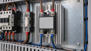
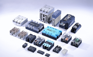
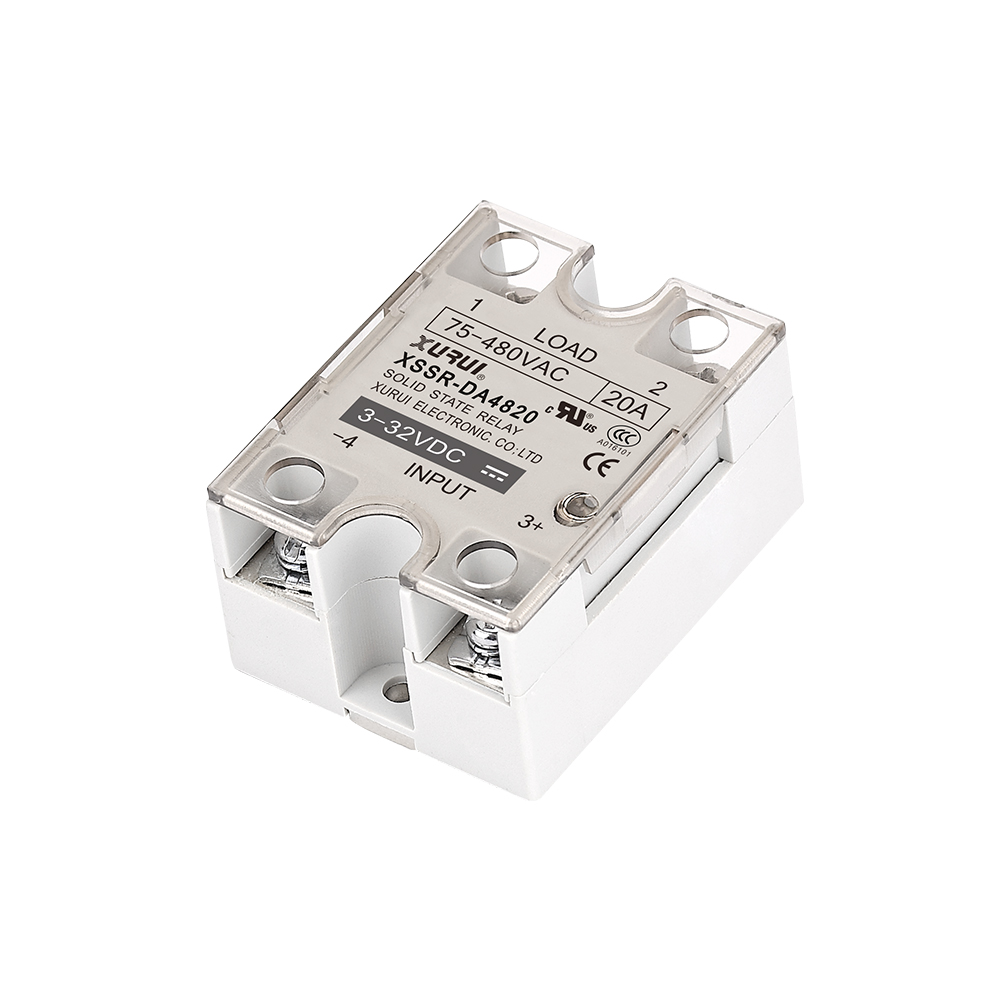
Solid-state relays (SSRs) switch loads through semiconductor junctions, such as SCRs, triacs, or MOSFETs, with no moving contacts. Optical isolation separates the 3–32 VDC control signal from the high-voltage load circuit. Response times are below 10 milliseconds, without contact bounce.
Zero-crossing SSRs turn on at the AC voltage zero crossing, reducing electromagnetic interference (EMI) and current surges in resistive heating loads. Random turn-on SSRs switch immediately, regardless of phase, for applications such as inductive solenoids.
Heatsink Sizing and Thermal Derating
The forward voltage drop produces about 1.0 to 1.2 watts of heat per switched ampere. That heat must leave the device to keep the semiconductor junction temperature, TJ, below its rated limit, typically 125°C.
Heatsink sizing follows this thermal resistance equation:
RJA=RJC+RCS+RSA=TJ-TAPD
Here, TA is the maximum internal enclosure temperature and PD is the dissipated power. The resistance terms describe the path from junction to case (RJC), across the thermal interface (RCS), and from heatsink to ambient air (RSA).
In sealed enclosures at 50°C to 60°C, SSRs need thermal derating unless adequately sized aluminum heatsinks and forced-air cooling can remove the heat.

Specifying Micro Switches for Shock and Vibration in Mobile Robots
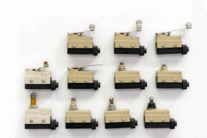
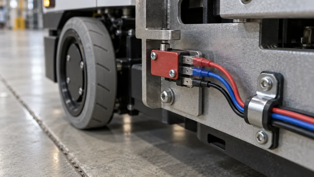
Autonomous mobile robots (AMRs) and automated guided vehicles (AGVs) expose snap-action switches to repeated impacts and vibration. These disturbances can interrupt signals and fatigue electrical connections.
Contact Chatter Under Repeated Shock
Floor joints, thresholds, and emergency braking send shock pulses through the switch blades. Closed contacts can briefly separate, producing contact chatter. Chatter lasting more than 1 microsecond triggers false homing signals, controller interrupts, or unintended safety stops.
For shock profiles up to 30 g, OEMs specify high contact force and stiffened beryllium-copper or phosphor-bronze leaf springs. Gold-plated bifurcated contacts provide redundant parallel contact paths.
Actuator and Contact Stability Under Vibration
Drive motors and rough flooring can excite resonance in internal snap blades, shifting the switch’s calibrated operating and release points.
Mounting the switch with the acceleration axis perpendicular to contact travel prevents vibration-induced separation. Pin plungers and short, rigid levers have higher natural resonant frequencies than long wire or hinge-roller levers, helping avoid sympathetic resonance during robot travel.
Terminal and Solder Joint Fatigue
Repeated vibration puts shear stress on terminals and solder joints. Unsecured wiring harnesses add mechanical loads and accelerate fatigue. To prevent fractures, use quick-connect terminals with strain-relief brackets, potted flying leads with IP-sealed entries, or screw terminals tightened to the specified torque.
Protecting Field-Level Sensing in Harsh Environments
Machining, chemical washdown, and outdoor handling expose switches to fluids, debris, and temperature extremes. Each exposure affects a different part of the assembly.
Coolant, Oil, and Ingress Protection
Synthetic coolants, cutting oils, and high-pressure chemical washdowns can penetrate standard IP65 enclosures and contaminate contacts. Demanding installations require IP67 or IP69K housings with fluoroelastomer (FKM) or nitrile butadiene rubber (NBR) seals, diaphragm plungers, and epoxy-potted wire cavities.
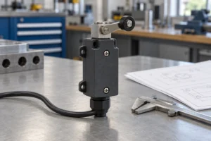
IP ratings alone do not establish compatibility with cutting fluids. The waterproof micro switch guide explains how the housing joints, actuator seals, cable entries, and mounting affect protection in the installed assembly.
Actuator Geometry and Jamming Prevention
Metal chips and other debris can jam a plunger or prevent it from resetting. Tight clearances between a cylindrical plunger and its bushing are particularly vulnerable to trapped swarf.
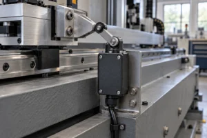
Roller levers with sealed bearings, chamfered housings, or flexible elastomer boots help shed debris. Cams should provide 30% to 50% overtravel beyond the operating point to accommodate mechanical tolerances without bottoming out the internal mechanism.

Operating Temperature Limits
At −40°C in automated cold storage, standard PVC cable jackets become brittle and return bellows stiffen, increasing operating force. At +80°C or higher on hot processing lines, thermoplastic housings soften and spring tension degrades. These conditions require switch variants with fluorosilicone gaskets, PTFE-insulated lead wires, and stainless-steel internal springs.
Functional Safety and Guard Interlocking
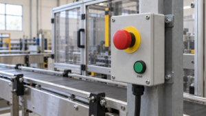
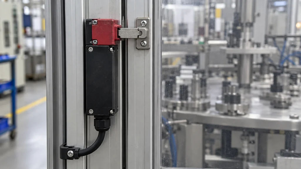
Safety standards and collaborative automation call for interlocks that reliably isolate hazardous motion and resist tampering. Start with the relationship between guard position and machine operation. This overview of safety interlock switch functions explains that relationship, along with alignment requirements and bypass prevention.
Interlock Reliability in ISO 13849-1
Under ISO 13849-1, the machine risk assessment establishes the required Performance Level (PLr). High-risk Category 3 and Category 4 architectures require redundant dual-channel monitoring, high diagnostic coverage (DC), and high mean time to dangerous failure (MTTFd).
A single standard switch cannot achieve Category 4 because of common-cause risks such as spring breakage or welded contacts. Dual-channel switches require monitoring by safety relays or safety PLCs.
Positive Opening Action
A return spring may fail to separate welded contacts in a standard switch. Safety interlocks must use positive opening operation under IEC 60947-5-1, Annex K. With positive opening, actuator movement drives a rigid mechanical link that forces the normally closed (NC) contact open. The link breaks contact micro-welds without relying on spring force.
Defeat-Resistant Guard Locking
Rotary cutters, flywheels, and other high-inertia equipment keep moving during run-down. Guards must stay locked until that motion stops. ISO 14119 requires measures against intentional bypass. OEMs use power-to-unlock switches with spring-applied mechanical locks, paired with RFID transponders or uniquely coded mechanical keys, to resist defeat with common tools.
Component Selection Matrix
The following matrix groups component choices by the operating problem they address.
| Application | Operating Challenge | Hardware Selection | Critical Specifications |
| High-Speed Indexing & Packaging | Rapid cycling; contact burnout; arc erosion | Zero-cross or random-on SSRs | 10 million equivalent cycles; optoisolation 2.5 kV; calculated RJA heatsink sizing |
| Autonomous Mobile Robots (AMRs) | Shock; continuous vibration; unstable logic signals | Bifurcated snap-action micro switches with high contact force | Shock 30 g; vibration 10–55 Hz at 1.5 mm; pin plunger |
| CNC Machining & Washdown Cells | Cutting oils; swarf; chemical washdown; actuator jams | Heavy-duty sealed limit switches with roller levers | IP67/IP69K; FKM seals; ≥ 30% actuator overtravel margin |
| Perimeter Safety & Guard Access | Bypass; inertia run-down; welded contacts | Solenoid guard-locking interlocks with coded keys | IEC 60947-5-1 Annex K direct drive; ISO 14119 Type 2/Type 4; locking force 1000 N |
SSRs do not provide a physical air gap for galvanic isolation. Upstream circuit breakers or mechanical disconnects remain mandatory for servicing. In safety interlock circuits, NC contacts connect to the safety circuit, while normally open (NO) contacts provide non-safety PLC status signals.
Total Cost of Ownership and Component Durability
The purchase price is only part of a component’s total cost of ownership (TCO). Field failures and replacement approvals can cost far more over the machine’s service life.
Field Failure and Warranty Costs
A failed switch can mean a technician visit, emergency shipping, and production downtime penalties. Those costs can exceed the original component savings by orders of magnitude. Switches tested for 10 million mechanical cycles, with self-cleaning wiping contacts, help reduce premature failures and warranty claims. Fewer failures also protect the OEM’s reputation.
Certification and Requalification Costs
Replacing an obsolete or non-compliant switch during production can require redesign, revised documentation, and recertification under UL 508, IEC 60947, or CE machinery directives. Manufacturers that maintain controlled product revisions and verified international regulatory listings help OEMs reduce this lifecycle risk.
To review component specifications, international certifications, and sample evaluation schedules, discuss operating conditions with XURUI. Include the thermal, mechanical, and safety requirements of the application.
Frequently Asked Questions
Will Smart Sensors Replace Electromechanical Switches in Industrial Automation?
No. Electromechanical contacts provide physical galvanic isolation that solid-state electronics cannot duplicate. Smart sensors support continuous diagnostics and non-contact proximity detection, while mechanical switches remain mandatory for primary emergency stops, hard travel limits, and fail-safe interlocks.
Can Conventional Switches Connect to IO-Link or Industrial Ethernet Networks?
Yes. Decentralized fieldbus I/O hubs connect conventional dry-contact switches to these networks. An IO-Link digital input hub collects binary signals from several switches and packages them into network telegrams for PROFINET, EtherNet/IP, or EtherCAT. Each switch does not need its own network card.
How Can OEMs Retrofit Legacy Equipment Without Replacing the Entire Control System?
OEMs can install drop-in multi-voltage SSRs, pre-wired sealed limit switches, and decentralized I/O blocks inside existing enclosures. SSRs with 3–32 VDC or 24–240 VAC control inputs replace worn mechanical relays without changing upstream PLC I/O cards. IP67-rated form-fit limit switches improve environmental protection without changes to mounting brackets.
External Sources
- ISO 13849-1: Safety of machinery — Safety-related parts of control systems
- IEC 60947-5-1: Low-voltage switchgear and controlgear — Part 5-1: Control circuit devices and switching elements
- ISO 14119: Safety of machinery — Interlocking devices associated with guards
- IEC 60529: Degrees of protection provided by enclosures (IP Code)