
A double-pole switch uses a single actuator to control two independent contact paths simultaneously. Depending on the circuit design, it can disconnect both energized conductors of a 240 V circuit or operate two coordinated contact paths.
“Double-pole” defines the internal contact logic, not electrical capacity. Voltage rating, continuous current, load type (resistive vs. inductive), and duty cycle determine whether a specific switch fits an application.
How Does a Double-Pole Switch Work?
A double-pole switch relies on an internal mechanical linkage to move two electrically isolated poles at the same time. Toggling the actuator opens or closes both paths together.
In a typical North American 120/240 V split-phase system, a properly rated double-pole switch disconnects both ungrounded (“hot”) conductors simultaneously, completely isolating a 240 V load from line power. For heavy-duty machinery and control panels, industrial lines like the XT Series toggle switch offer dual-pole configurations engineered to handle these high-demand AC and DC circuits.

What Are the Main Types of Double-Pole Switches?
The two primary types are DPST and DPDT. In industrial toggle switches, models also vary by terminal style, environmental sealing, and electrical ratings to meet different operational demands.

Double-Pole Single-Throw Switch
A double-pole single-throw (DPST) switch functions as a synchronized dual ON/OFF switch. A standard model has four terminals, with two assigned to each pole.
DPST switches are ideal when two conductors or control paths must turn on and off together. Terminal pinouts vary across manufacturers, so consult a DPST switch diagram to verify paired contacts rather than assuming adjacent terminals share the same pole.
Double-Pole Double-Throw Switch
A double-pole double-throw (DPDT) switch routes two input (common) lines between two sets of output (throw) terminals, using six terminals in total.
An ON-ON configuration alternates between two active circuit paths. An ON-OFF-ON version adds a center-off position that leaves both poles open for neutral standby. These setups are widely used for signal routing, dual-source selection, and polarity reversal. Refer to a DPDT switch diagram to trace how common terminals connect to throws in each toggle state.
What Are the Common Uses of a Double-Pole Switch?
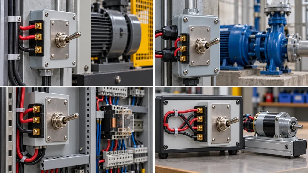
Double-pole switches are used when two contact paths need to change state through one mechanical action. Primary applications include equipment isolation, motor switching, multi-circuit coordination, and polarity reversal.
Disconnecting Two Conductors for Equipment Isolation
A rated double-pole disconnect breaks both ungrounded conductors supplying equipment. In a 120/240 V split-phase system, this fully isolates a 240 V load instead of leaving one live leg connected.
This alone does not make the equipment safe for maintenance. Workers must follow formal Lockout/Tagout (LOTO) procedures, verify de-energization, and discharge stored energy. Control-circuit switches and push buttons do not qualify as primary energy-isolating devices.
Switching Motors and Industrial Equipment
Double-pole switches can control single-phase motors, pumps, and fans provided the device carries an appropriate horsepower (HP) or inductive rating. Motors draw substantial startup inrush current and generate inductive arcing upon interruption. A resistive-load ampere rating alone is never sufficient evidence that a switch can safely handle motor duty.
Controlling Two Independent Circuits Simultaneously
A double-pole switch can coordinate two electrically isolated circuits using one toggle. For example, one pole may operate a power circuit while the other provides a control signal, but only when the exact switch is rated for both circuit voltages and load types and its insulation, spacing, terminal arrangement, and certification permit the circuits to share one device. If the switch lacks sufficient internal spacing or mixed AC/DC ratings, an interposing relay should be used instead.
Reversing DC Motor Direction With a DPDT Switch
In a cross-wired polarity-reversing circuit, a DPDT switch reverses a permanent-magnet DC motor by swapping the polarity applied to its leads. Terminal wiring must follow the specific model’s layout, and the switch must carry a dedicated DC rating matched to the motor’s operating and stall currents. An ON-OFF-ON model provides a center-off position for Forward, Stop, and Reverse control.
How Is a Double-Pole Switch Different From a Single-Pole Switch?
A single-pole switch controls one contact path, while a double-pole switch controls two mechanically linked paths in one motion. Pole count indicates circuit logic rather than load capacity.
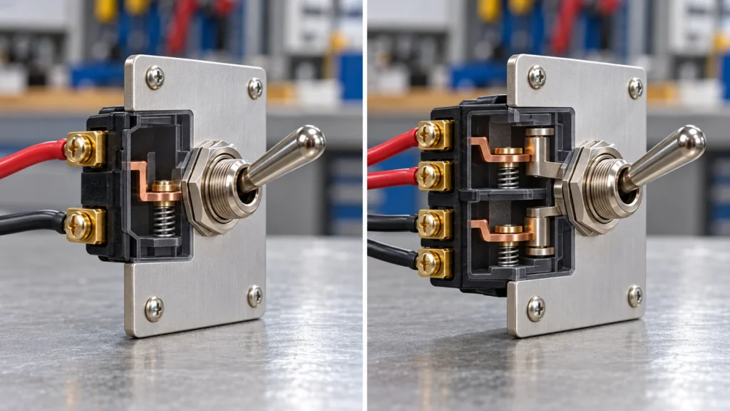
| Feature | Single-Pole Switch | Double-Pole Switch |
| Controlled Paths | 1 contact path | 2 mechanically linked paths |
| Basic Terminal Count | 2 (SPST) or 3 (SPDT) | 4 (DPST) or 6 (DPDT) |
| Primary Function | Controls a single conductor/load | Controls two conductors or dual circuits |
| Typical Application | Standard 120 V lighting/loads | 240 V loads, polarity reversal, dual circuits |
| Rating Requirements | Circuit voltage and current | Ratings for both poles plus pole-to-pole insulation |
| Operation | 1 pole changes state | 2 poles change state via 1 actuator |
A double-pole switch is also fundamentally different from a 3-way switch. In North American building wiring, two 3-way switches work together to control a single load from two locations. “Double-pole” refers entirely to the number of separate paths switched inside one device.
How Can You Identify a Double-Pole Switch?
You can identify a double-pole switch by its terminal count, schematic markings, and datasheet:
- Terminal Count: Standard DPST models feature 4 circuit terminals; DPDT models feature 6. (Ground lugs, illumination pins, or auxiliary terminals may increase this count).
- Continuity Testing: With the switch completely de-energized and disconnected from all wiring, use a multimeter’s continuity mode to map which terminals bridge in each actuator position.
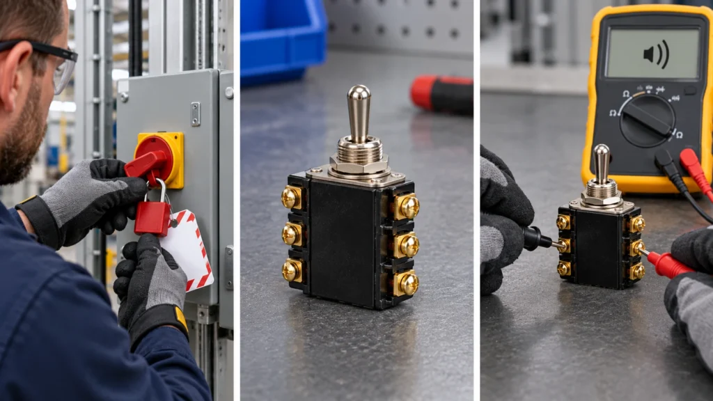
For custom configurations or model verification, submit project specifications including voltage, inrush load, terminal style, and environmental requirements to confirm component suitability.
Frequently Asked Questions
Can You Use a Double-Pole Switch on a 120 V Circuit?
Yes. A rated double-pole switch can be used on a 120 V circuit. A neutral may be switched only when the approved arrangement disconnects the required conductors together; the equipment ground must remain connected. The equipment ground conductor must never be switched.
What Is the Difference Between a Double-Pole Switch and Two Separate Switches?
A double-pole switch mechanically links two contacts so they operate together, although a fault may prevent one contact from changing state. Two separate switches operate independently, introducing the risk of operator error where one line is opened while the other remains dangerously energized.
When Should You Use a Switch Instead of a Double-Pole Circuit Breaker?
A switch provides manual operational control and local disconnect capability, but standard switches offer no overcurrent protection. A circuit breaker provides automatic overcurrent and short-circuit protection. An installation may use separate switching and overcurrent-protection devices or one device approved for both functions.
Which Conductors Does a Double-Pole Switch Disconnect?
In a 240 V split-phase setup, it disconnects both ungrounded (“hot”) conductors. In dual-circuit applications, it disconnects whichever specific line is routed through each independent pole. It must never disconnect the equipment ground.
External Sources
- Eaton Switch Terminology Glossary
- OSHA 29 CFR 1910.303: General Electrical Requirements
- OSHA 29 CFR 1910.304: Wiring Design and Protection
- OSHA 29 CFR 1910.147: Control of Hazardous Energy
- UL Solutions: Machine Supply Circuit and Disconnecting Means
- DigiKey: Bi-Directional DC Motor Control With DPDT Switches