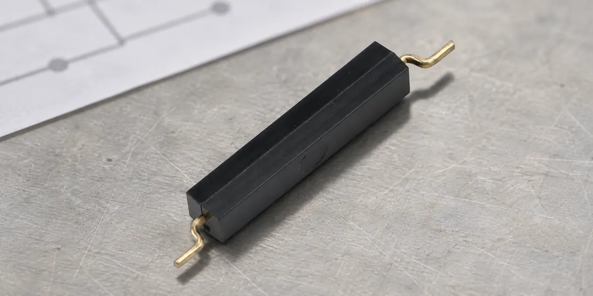
A reed switch symbol shows magnetically operated contacts in a defined reference state. Read the contact arrangement, then trace how its connections change when the operating magnetic field is applied.
This guide covers normally open, normally closed, and changeover contacts. It explains how to follow their circuit paths and distinguish contact behavior from door position, wire count, and physical pin layout.
What a Reed Switch Symbol Shows
The contact lines show where an electrical path opens or closes. A nearby magnetic actuation mark or label identifies how the switch operates.
Look for these features:
- A gap between contact lines indicates an open connection.
- Touching contact lines indicate a closed connection.
- A moving contact between two fixed contacts indicates changeover operation.
Some drawings enclose the contacts in an oval or rectangle. Read this outline together with the drawing legend and device label; its shape alone does not identify the contact function. Reed switches have physical electrical contacts that a magnet operates without touching the housing. Powered electronic outputs may instead need supply and signal connections.
Here, reference state means the manufacturer’s specified condition before external magnetic actuation. The state comparisons cover ordinary non-latching devices. Latching devices can retain their state after the operating magnet is removed.
Reed Switch Contact Symbols
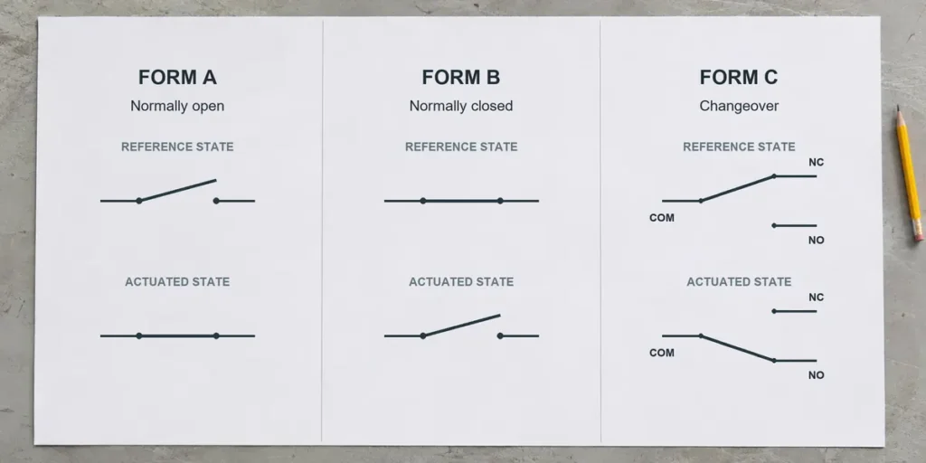
Form A, Form B, and Form C identify the contact arrangements. Use these designations to confirm what the contact lines show.
Normally Open (Form A)
A Form A contact pair is open in its reference state. A suitable magnetic field brings the contacts together, completing the path between the two leads. This arrangement is SPST-NO: single pole, single throw, normally open. It controls one circuit through one contact path. The symbol’s gap identifies the open connection, but it gives no operating distance. Normally open reed switch sensing depends on magnetic sensitivity, alignment, and motion.
Normally Closed (Form B)
A Form B contact pair is closed in its reference state and opens under external magnetic actuation. Its arrangement is SPST-NC: single pole, single throw, normally closed. Some NC assemblies use a bias magnet to hold the reference condition. Their normal state therefore includes a magnetic field. The symbol describes the contact behavior without identifying its internal construction.
Changeover (Form C)
A Form C reed switch transfers a common connection between two fixed contacts. This arrangement is SPDT: single pole, double throw. COM is the common terminal. In the reference state, it connects to NC, the normally closed contact. Actuation transfers the connection to NO, the normally open contact. Form C uses break-before-make operation: the existing connection opens before the other closes. The two paths share COM, so they are not independent switched circuits.
The table compares the reference and actuated states. Actuation requires a magnetic field with the appropriate strength and orientation.
| Contact Form | Reference State | Magnetically Actuated State | Contact Arrangement |
| Form A | Open | Closed | SPST-NO |
| Form B | Closed | Open | SPST-NC |
| Form C | COM–NC closed; COM–NO open | COM–NC open; COM–NO closed | SPDT / Changeover |
How to Trace a Reed Switch in a Circuit Diagram
First establish which contact path is continuous. Current can flow through that path only when a power source and the rest of the circuit complete the loop.
Step1: Confirm the Reference State
Read the drawing notes or legend to determine the condition shown. Begin with the specified unactuated state unless the drawing states that the contacts are shown in an operating condition. Turning off machine power does not necessarily release a reed contact. A permanent magnet may still hold it in the operated position.
Step2: Identify the Contact Terminals
Match the schematic connections to the device’s terminal diagram. Identify the contact pair on a two-terminal device, or COM, NC, and NO on a changeover device. Record the terminal numbers or wire identifiers beside their functions. For the XGH Series reed switch, use the drawing for the exact model and suffix. The series name alone does not establish the terminal assignment.
Step3: Compare Contact Paths Before and After Actuation
Trace the continuous path in the reference state, then follow the connection after actuation. Suppose a Form C switch has COM connected to a supply, with NC and NO feeding separate signal branches. In the reference state, COM connects to the NC branch. Actuation opens that branch and connects COM to the NO branch. Follow each branch to its load or controller input. The surrounding circuit determines whether contact closure produces an active signal.

Common Reed Switch Symbol Reading Mistakes
Door position, wire count, and lead location can cause confusion when read without the contact diagram.
Confusing Door State with Contact State
A Form A switch can close when a door shuts because the door brings the magnet into operating range. Opening the door moves the magnet away and lets the contacts open. The closed door describes the installation’s mechanical position. The normally open designation describes the contact’s reference state. Record both when interpreting an alarm circuit.
Assuming Three Wires Mean SPDT
Inspect the terminal labels before assigning a function. COM, NC, and NO identify changeover connections. Positive supply, ground, and output identify a powered sensor or module. This distinction also matters when reading proximity switch symbols. Establish each terminal’s function before connecting power.
Confusing Symbol Layout with Pin Layout
A schematic shows electrical relationships. Use the manufacturer’s connection drawing to locate the physical leads. COM may appear on the left of a symbol without being the component’s leftmost lead. The upper fixed contact likewise has no universal pin number. Match the functions to the numbered pins, using the drawing’s stated top or bottom view. Wire color alone is not enough to assign a function.
For help reviewing a connection, send your schematic and model details to XURUI. Include the required contact state and signal voltage and current to help identify a suitable contact arrangement and electrical rating.
Frequently Asked Questions
Is a Three-Wire Reed Switch Always SPDT?
No. A three-wire reed sensor may include circuitry with power and signal connections. An SPDT connection diagram identifies COM and separate NC and NO paths. Use those terminal assignments to confirm the function.
How Does a Reed Relay Symbol Differ from a Reed Switch Symbol?
A reed relay diagram includes a drive coil and its reed contacts; the reed switch symbol alone shows the contact element. The coil and contacts may appear together or separately under the same device identifier. Keep their terminals separate, and do not use the coil voltage as the contact voltage rating.
Does a Reed Switch Symbol Show Its Current Rating?
No. The exact model’s data sheet lists its switching and carry current limits. Switching current applies during contact operation. Carry current applies once the contacts are closed. The circuit must also stay within the specified voltage, switching power, and load conditions.
External Sources
- Reed Switch Developments — Reed Switch Operation
- Standex Detect — Magnet Interaction
- Reed Sensor Dynamics — Ways of Actuating a Reed Switch
- Reed Sensor Dynamics — Form C
- Pickering Electronics — Series 106 Reed Relay Data Sheet
- Standex Detect — Basic Electrical Parameters of Reed Switch Products